Hi! You are probably visiting this page because you have just get a Bhoreal controller or you are thinking about getting one.
If you are one of the former group, congratulations on being the owner of a brand new Bhoreal controller! The Bhoreal team wants to thank you for purchasing a controller, joining the community and taking part on this adventure.
If you are one of the latter, thanks a lot for your interest in Bhoreal. We are eager for users who have a similar approach to the understanding and development of open source tools. We would like to invite you to join our community!
You can also check this project in GitHub if you want.
In any case, thank you for being here.
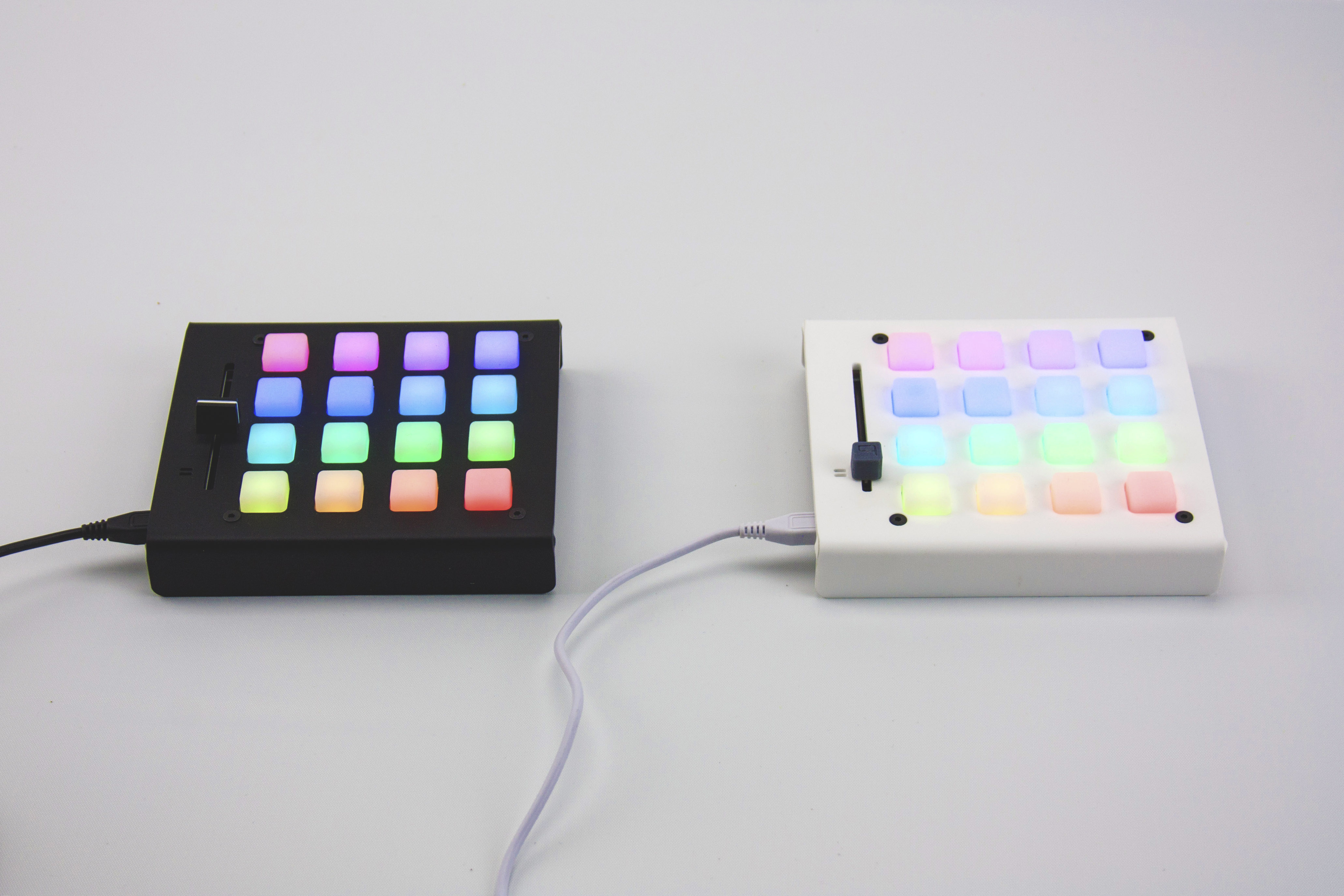
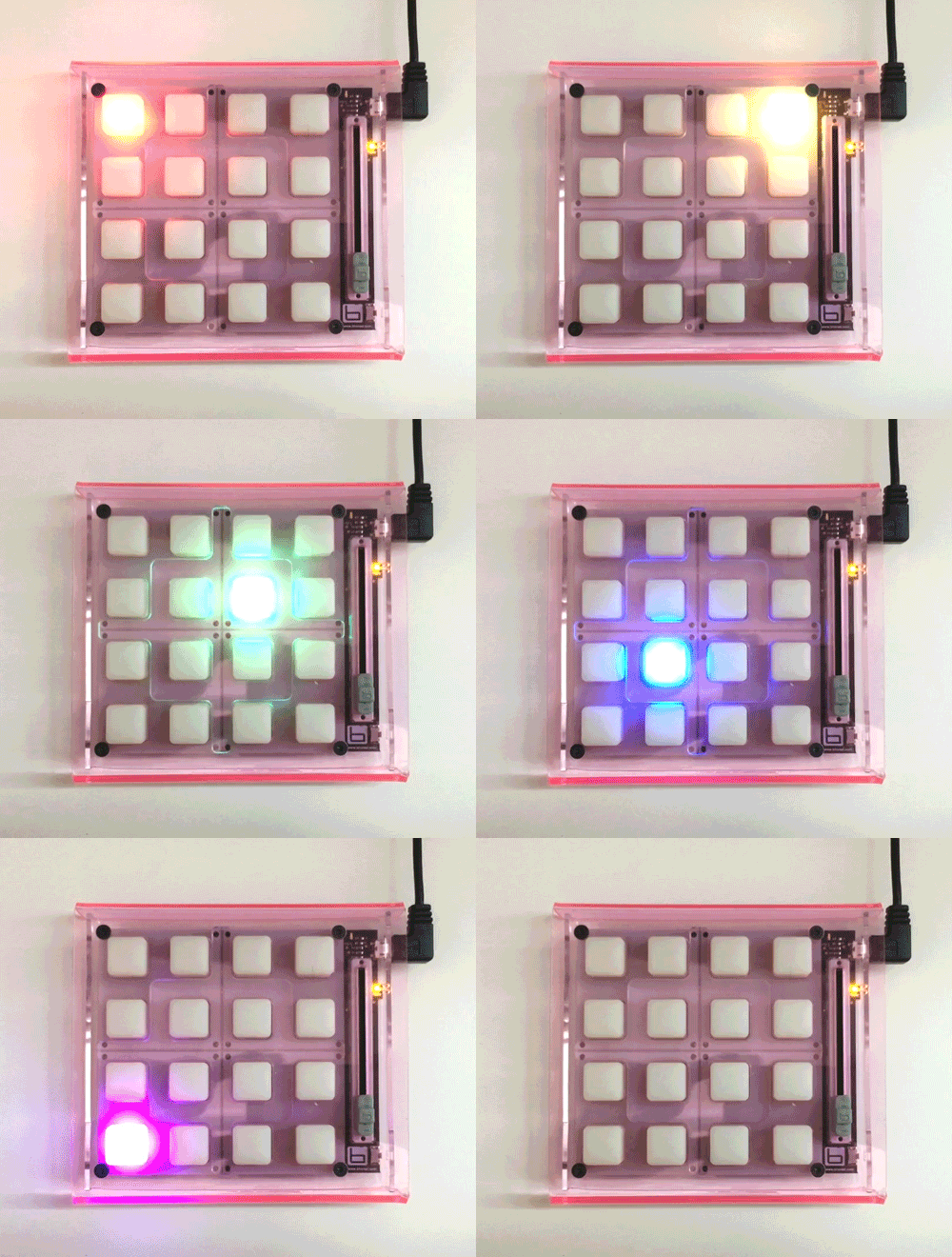
All Bhoreal control interfaces have a minimalist design. Its external appearance is extremely simple, with a square shape and backlit buttons, without icons or marks. They don’t generate sounds by itself. They’re a blank slate, without any autonomous function. You have to connect them to a computer and associate them to a software in order to work. When you connect Bhoreal controller to a computer, begins a startup test program and the buttons blink. Each button has its own LED and surprise! They’re RGB!
Open Source philosophy is present in both hardware and software design. The firmware is Open Source and all the documentation is released under Creative Common licenses. We love Open Source and we hope you love it too!
This is the support page for Bhoreal documents. You can find here all the information you need to get to know all about your controller. You can test if it works correctly as soon as you take it out from the box, also reprogram the firmware in order to use Bhoreal with your favorite software applications.
A document with these features is too large, so we decided to divide it into seven groups of general interests: GETTING STARTED, HARDWARE, FIRMWARE, SOFTWARE, COMMUNICATION, PROGRAMMING and CASES.
These big big groups are divided into more specific subgroups. For example, if you want to know more about the LEDs that are used for a Bhoreal controller, you should go to HARDWARE section. If you want to know how to work the serial protocol of Bhoreal, you need to go visit COMMUNICATION section.
There is also a general section of TROUBLESHOOTING where you can find the solutions for the most common problems that you may be faced with, when you start to use a Bhoreal controller. This is not a finished document and will be modified in parallel with the project evolution. It will be very welcome any kind of comment related to improve the contents or the structure itself.
This documentation is managed by Bhoreal, but supported by the community. We welcome contributions such as:
- Edits to improve grammar or fix typos
- Additional annotated examples for others to follow
- Additional content that would help provide a complete understanding of the Bhoreal controller
Making a contribution is as simple as forking this repository, making edits to your fork, and contributing those edits as a pull request. For more information on how to make a pull request, see github help.
Some of this documentation is derived from the Arduino documentation, as the Arduino language and libraries.
This documentation is built using Flatdoc, an awesome tool for building beautiful documentation from simple Markdown files. Some template features are based on the Spark project documentation by Spark Labs, Inc.
All the contents on this page are published under a Creative Commons license:
Creative Commons Attribution - Non Comercial - Share Alike 3.0 License (CC BY-NC-SA 3.0).
You must give appropriate credit, provide a link to the license, and indicate if changes were made. You may do so in any reasonable manner, but not in any way that suggests the licensor endorses you or your use.
You can not use the material for a commerical purpouse.
If you remix, transform of develop from this material, you may distribute your contributions under the same license as the original.
To learn more about this license and others visit: http://creativecommons.org/licenses/
Connect your Bhoreal Mini to a computer using a micro USB cable, which is used for the most of smartphones or cell phones. In any case, be assured that the micro USB cable you use allows the device load such as the data transfer.
The device will be charged by USB connection, and as soon as connect it, the boot sequence will be run. This boot sequence is a gradient color wheel HUE.
Once your controller is switched on, it’s ready for use through some application or software pack, which is compatible with MIDI and Serie protocol.
You can download the test application on the following link to check if your Bhoreal works correctly and understand the communication protocol in the best way:
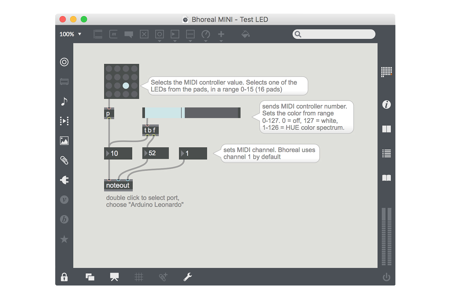
The Bhoreal Test application uses MIDI protocol to communicate with the hardware. We need to open a corresponding midi port to send and receive MIDI from Bhoreal. Bhoreal is an Arduino based project and the MIDI port appears under the name of “Arduino Leonardo”. Once the MIDI port is selected the device is ready to send and receive data.
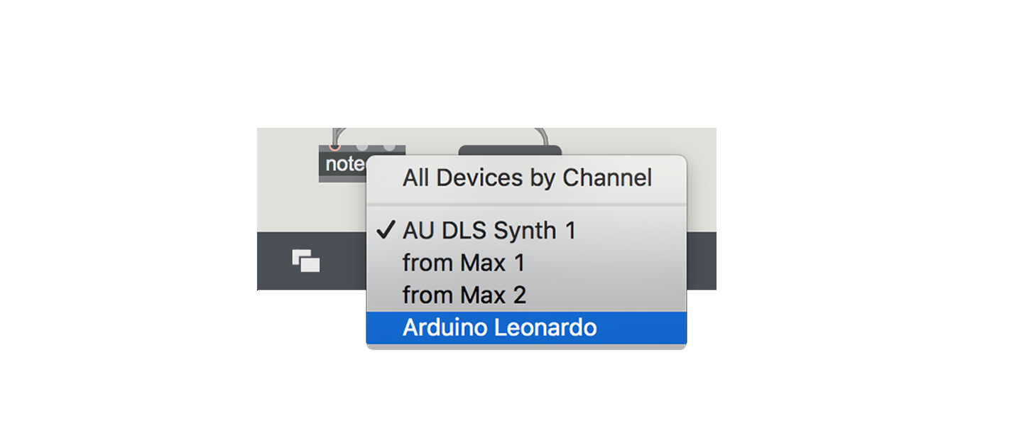
In the test application, the MIDI input is configured to receive from any device, but you should double-click on noteout and select “Arduino Leonardo” as mentioned.
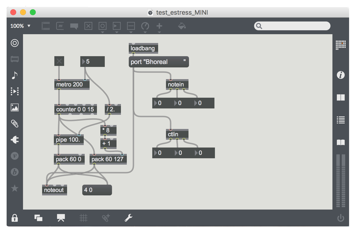
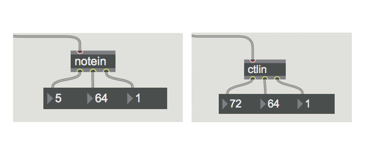
The test application works as a MIDI monitor where you can see the messages that "you’re sending" when you press a button or move the slider (notein and ctlin).
Also you can generate a sweep sequence that scans the LED screen using the same colors as the boot sequence, just toggle the "[X]" button above metro 200. Here we can see how the MIDI protocol works, which is detailed in the communication section.
There is an other Bhoreal Test application you can download here, where you can play with the different MIDI messages the Bhoreal can receive for LED color change.
If you want to learn more about your Bhoreal device, you can keep reading the following sections where we will explain you with details about the hardware and its components, how to install the programming environment, the communication protocols, the programming languages and the most important functions of the firmware, with dozens of examples that third-party software uses.
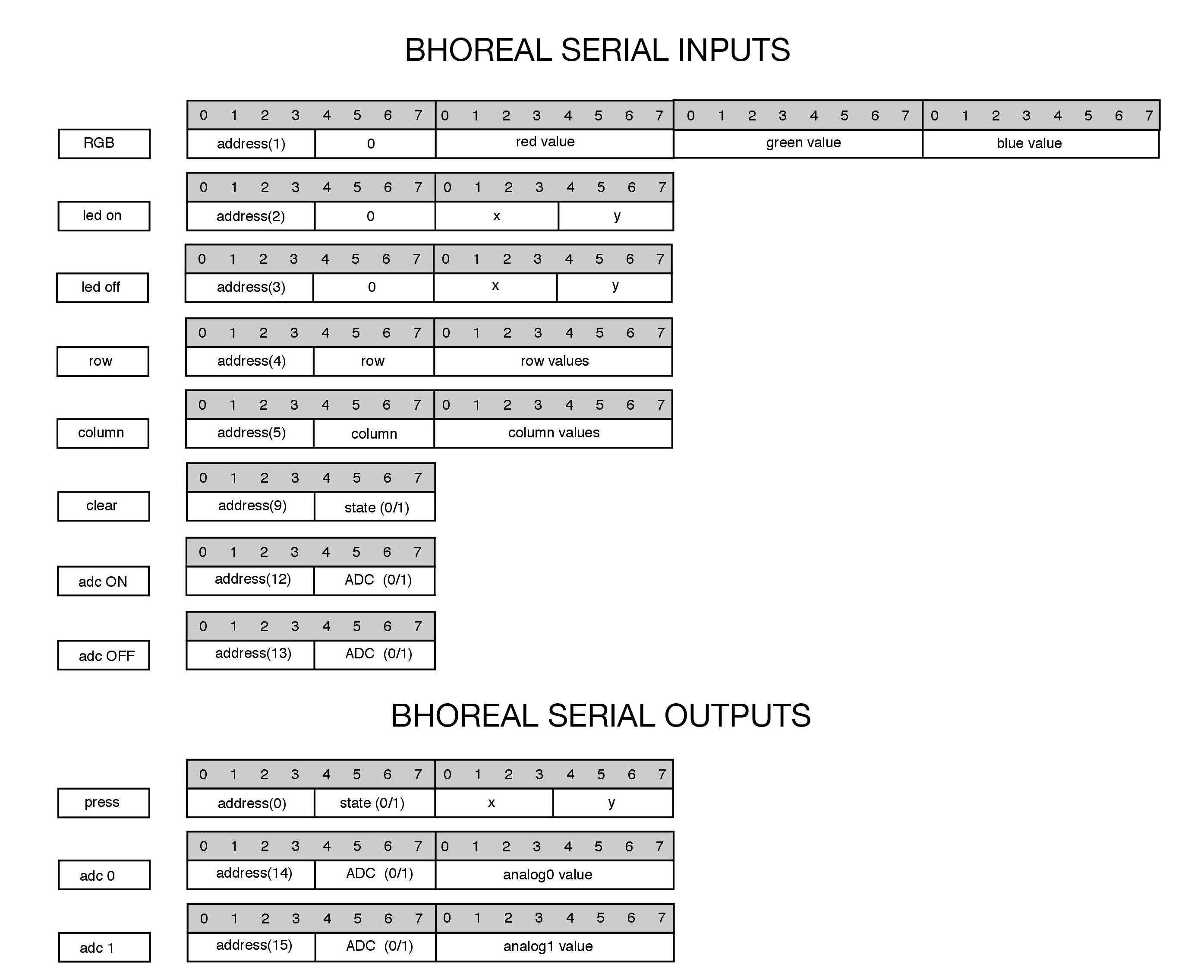
Bhoreal can use two communication protocols: Serial and MIDI, but the MIDI protocol is the prior and will be used for the most of available applications.
Now, we will show you the current command document, these commands can be expanded in the future adapting the user's needs.
Also it's possible that each person could use their own code and commands as open firmware is used, and anyone can access to the code.
If someone develops something interesting in this sense, we’d like to ask them to share it with the rest of the community, using any of the available tools or by making full requests to this documentation.
#include <Arduino.h>
#include <Wire.h>
#include <avr/pgmspace.h>

#define  MINI  			0  //Matrix size
#define  SLIM  			1  //Matrix size
#define  SLIMPRO  		2  //Matrix size

#define  SERIAL_ENABLE  1
#define  MIDI_DEBUG     1
#define  SERIAL_DATA    0

#define  TOOFULL 		100

#define  MODEL  MINI 		//Model
//#define  MODEL  SLIM 		//Model
//#define  MODEL  SLIMPRO 	//Model
The Serial communication - also known as RS-232 - is based in the serial transmission of information through a bidirectional data cable. The communication is asynchronous with 8 bit packages and always needs an additional bit for the synchronization. This makes high velocities can not be reached, being 115200 Bd (bauds) the higher one recommended for Bhoreal.
Bhoreal uses the same serial protocol as Arduino to communicate with the programming tool, this protocol is always used whenever a firmware update is done. Bhoreal serial port levels are TTL, that is to say, the ‘0’ logic corresponds to 0 volts and the ‘1’ logic corresponds to 5 volts on the bus.
To activate the serial communication with Bhoreal it’s necessary to turn on the firmware flag, which comes disabled by defect. This is because the communication becomes a bit slower when the MIDI and the Serial are used simultaneously. Therefore, the users are free to select a communication port or any other port, simply turning on these flags (#define SERIAL_ENABLE and #define MIDI_DEBUGat the beginning of Bhoreal.h).
You can see the available serial commands in the image.
The MIDI communication is a specific serial protocol which were started to use in the 80’s, to communicate among digital musical instruments. The MIDI protocol has many followers maintaining the compatibility with the most of audio/video softwares in real time.
The MIDI in Bhoreal is Compliant USB MIDI. This means it works with a standard library that doesn’t require external drivers, which makes very easy the installation. Plug and play!
The compatibility of Bhoreal with MIDI USB Compliant, unlike to Arduino, is because of the use of a specific Hardware Core that enables the MIDI functions on the firmware. For that, we’ve relied on the open source project ARCORE. Check out the installation section of programming environment for more information.
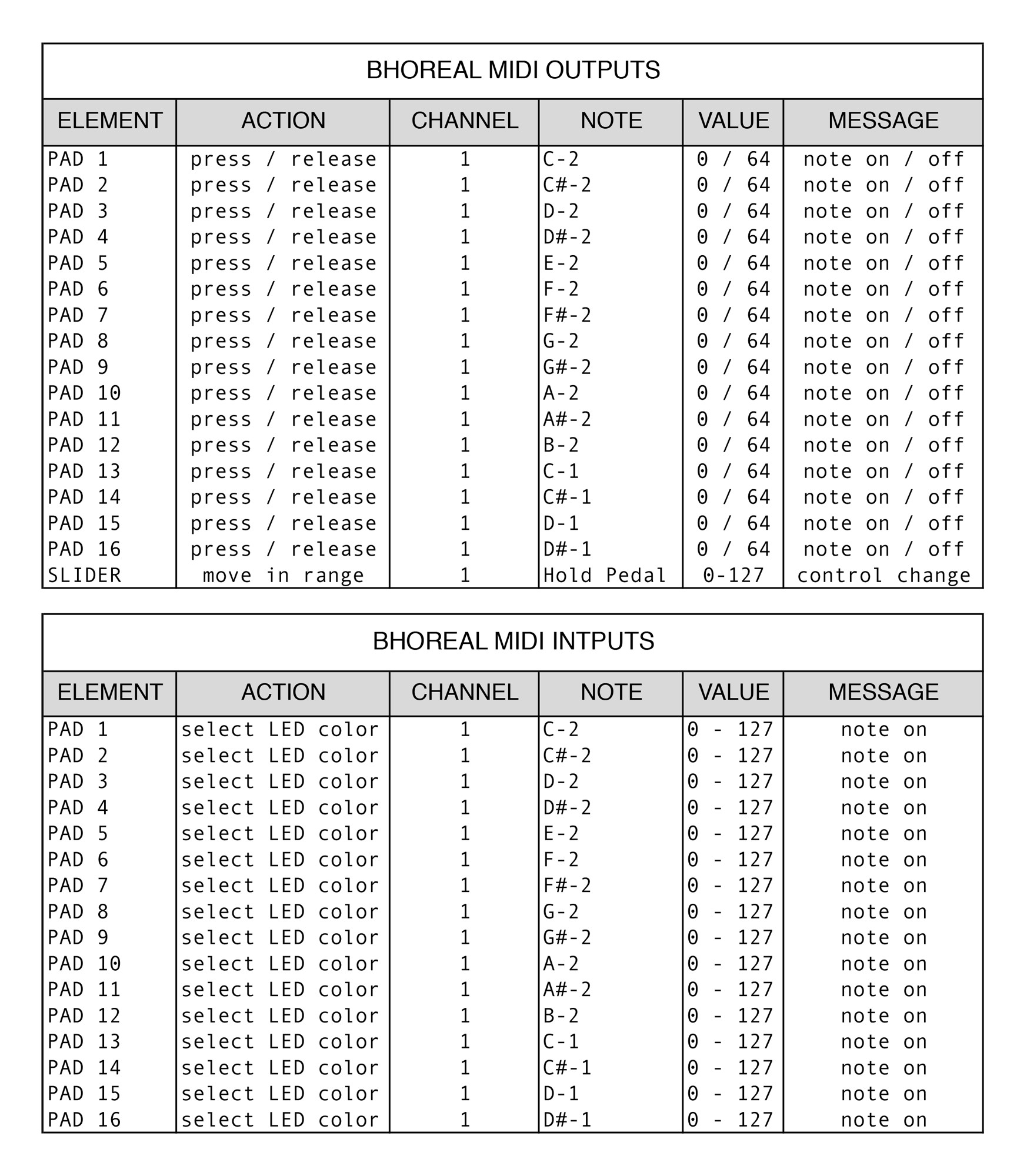
You can see the available MIDI commands in the image.
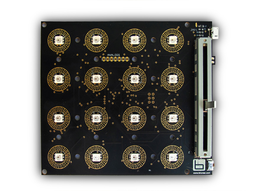
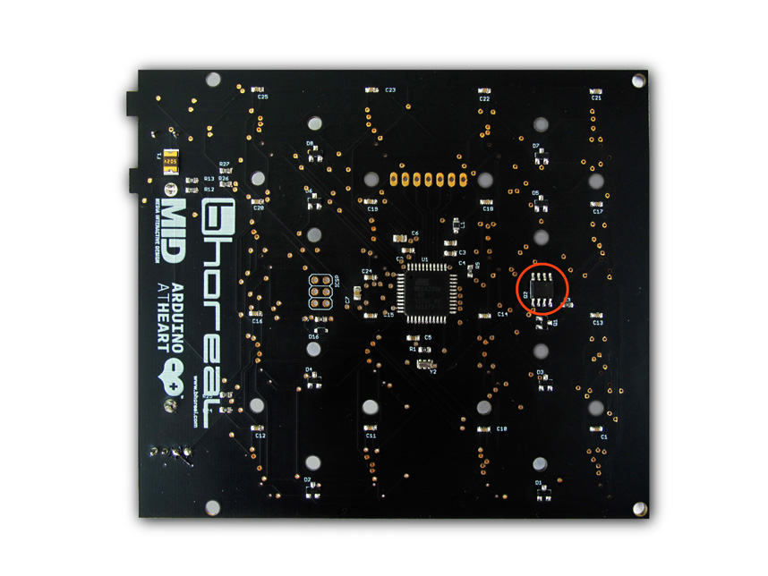
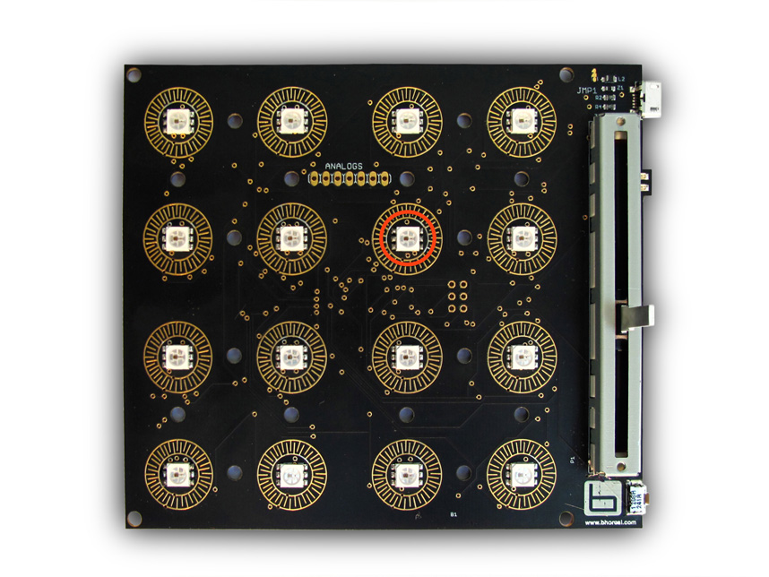
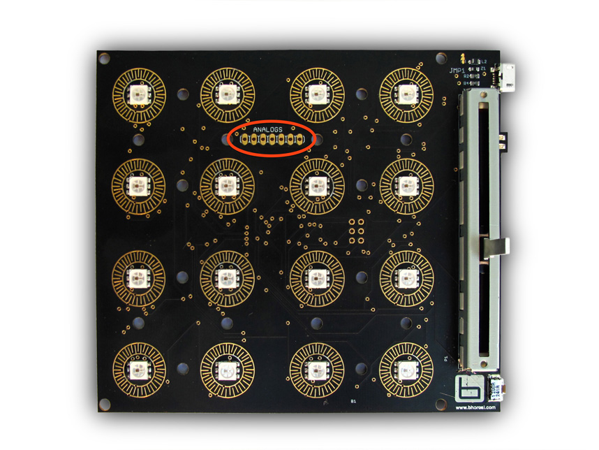
The first image corresponds to the top of the board.
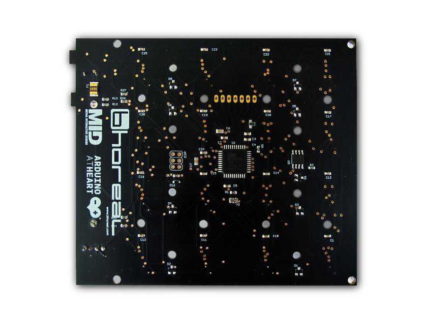
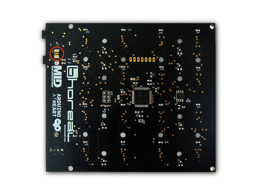
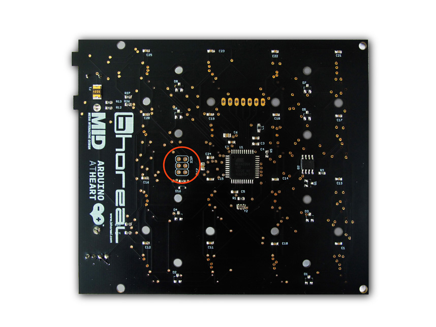
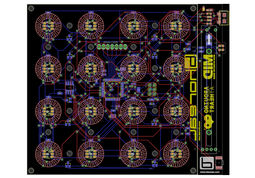
The second one to the bottom of the board.
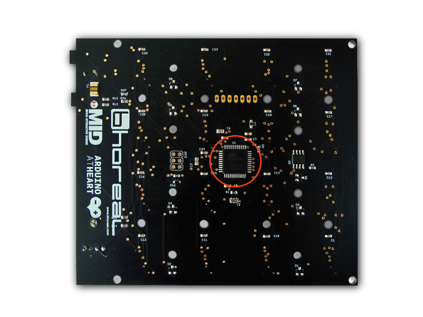
The Bhoreal Mini Slim uses the ATmega32U4 microcontroller for its processing power. You can download the datasheet here.
Some of its key features are as follows:
- 16Mhz operating frequency
- 12 KB of Flash memory
- 8-bit AVR
- 2.5 KB of SRAM
- 10 bit ADC
- USB 2.0 full-speed interface
- USART, SPI and I2C interfaces
- JTAG Debug mode
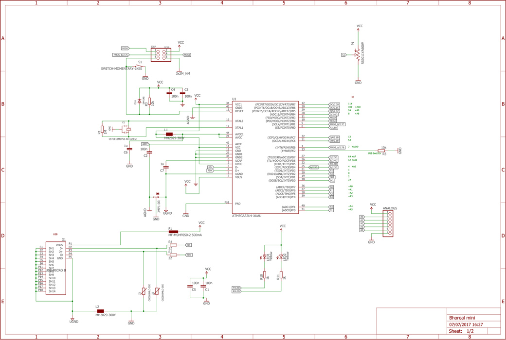
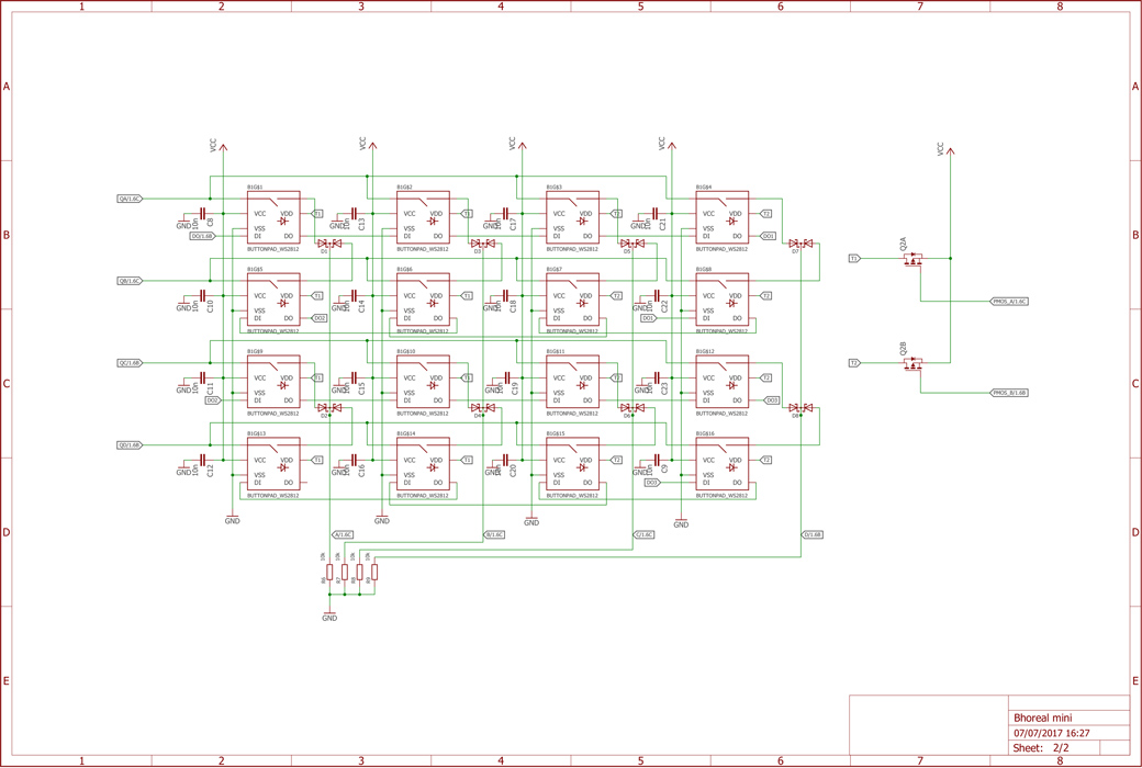
There are two transistors on the PCB that have a very important role for the electronic operating: Q1 and Q2. Those Mosfests are in charge of the screen refresh control. Since the consumption of the LED matrix to maximum intensity exceeds the maximun the USB port allows (500 mA), we’ve chosen the strategy of multiplexing the screen control. For that, we’ve made two groups of independent LEDs, which are controlled by Q2a and Q2b, they alternate to divide into two the consumption and the light intensity. Q1 is a control signal investor that acts on Q2b, while Q2a is connected directly to this signal. This frequency is controlled by firmware and is very high, so we couldn't notice the blinking of the screen. This is possible because the WS2812 has two independent VCC lines, one for the LED and the other for the digital driver WS2811, embed in the LED capsule.
The Bhoreal Mini Slim board has a resettable polyfuse that protects your computer's USB ports from shorts and overcurrent. Although most computers provide their own internal protection, the fuse provides an extra layer of protection. If more than 500 mA is applied to the USB port, the fuse will automatically break the connection until the short or overload is removed.
The connector In Circuit Serial Programming or commonly called ICSP allows to reprogram the microcontroller ATmega32U4 from a compatible external programmer. This method allows to restore the device bootloader completely or update it, if it’s necessary.
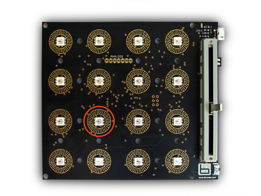
Bhoreal Mini incorporates 16 SMD RGB digital LEDs and 2 yellow LEDs for signals. In case of RGB digital LED, the used model is the WS2812 with 6 pins. They stand out because of the use of the control chip wS2811, embed within the LED, simplifying a lot the external electronics and the space the boards occupy. This type of digital LEDs are waterfall direccionables. The data is transferred one by one through the DIN and DOUT pins, which work as a high-speed serial port, so, for the control of microcontroller, it only needs a data pin. The data refresh frequency is 800Kbps. The power for the LEDs and the control chip is splitted, and that allows a very fast multiplexing of the LEDs, therefore, an optimization of energy consumption.
There are also two yellow LEDs on the Board to show the state of serial and MIDI communication port.
You can download the datasheet here.
Features:
- Viewing angle: 120 degrees
- Red: (620-630nm) @ 550-700mcd
- Green: (515-530nm) @ 1100-1400mcd
- Blue: (465-475nm) @ 200-400mcd
Forward Voltage:
- Red: 1.8-2.2V
- Green: 3.0-3.2V
- Blue: 3.2-3.4V
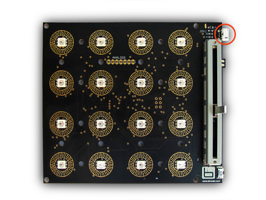
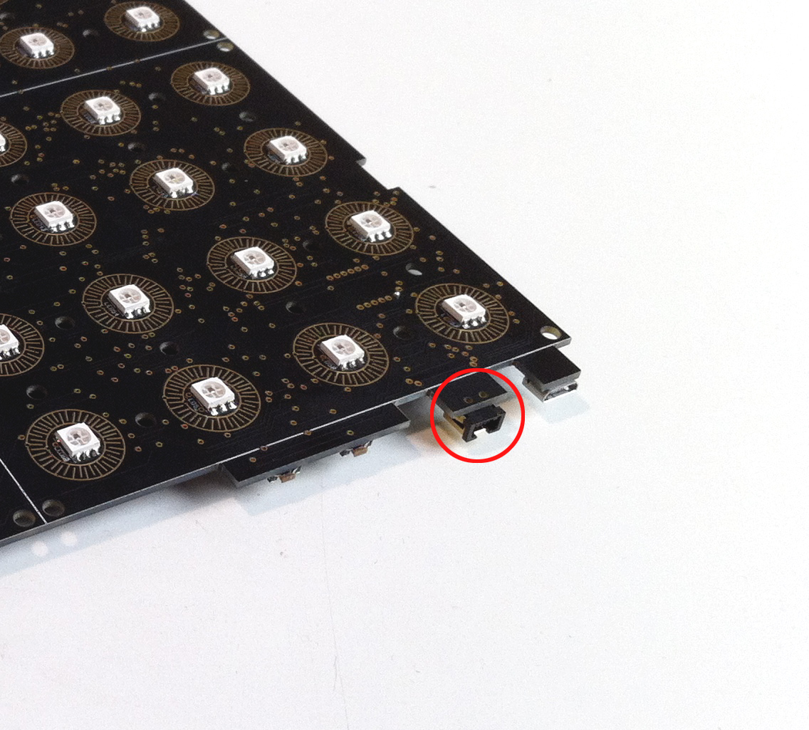
Bhoreal Mini has a Micro USB connector that enables the connectivity between the device and the USB communication port. Simply connect it to a computer with a micro USB cable to get started.
The translucent silicon keypad has 16 buttons and is based on the original design of Sparkfun, and considering the perfect function with SMD WS2812 LED which are used for the Bhoreal board. Each one of the buttons has a conductive ring at the bottom that works as a switch when the conductive surfaces of the PCB is slightly pressed.
There are two keypad models adapted the different type of LEDs.
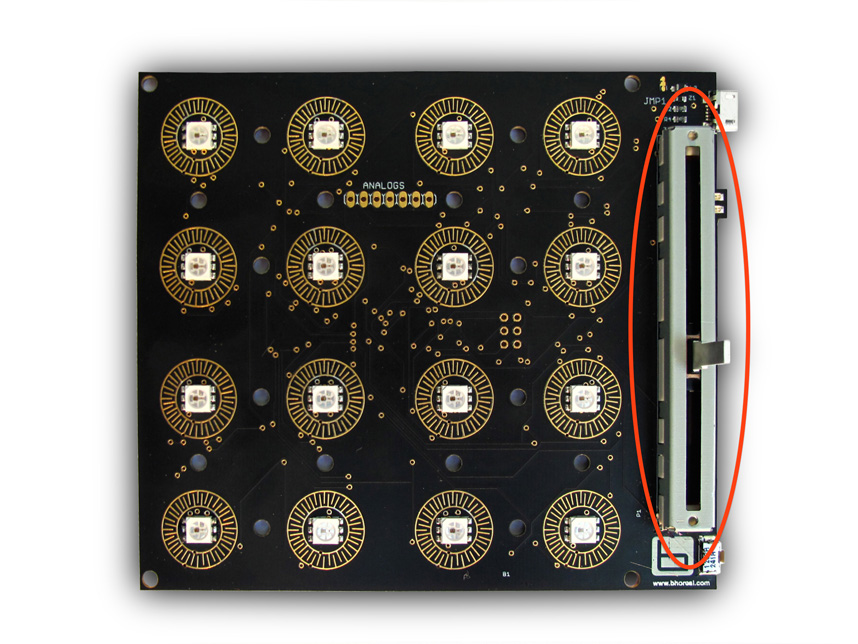
Bhoreal Mini Slide version has a 60mm slide potentiometer. With this slider you can send the lineal position datas in real time through the USB port, or interact with LED matrix.
You can download the datasheet here.
Features:
- ALPS RS6011YA6009
- 10 kOhms Linear potentiometer
- 9 mm W x 75 mm L
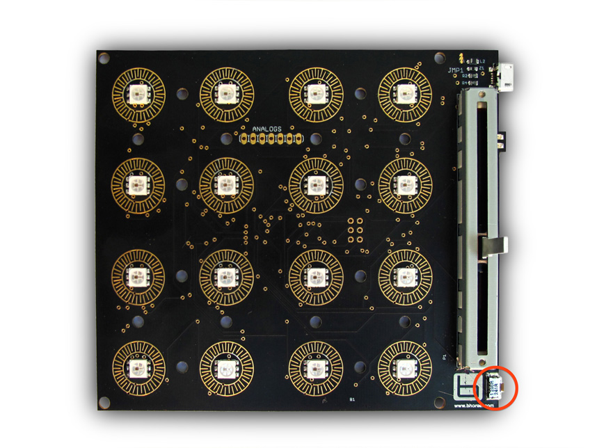
The Reset push button allows to reset the microcontroller and to reboot the firmware. This button activates the Reset circuit which is 100% compatible with Arduino Leonardo.
Bhoreal Mini has expanding pins that allows to extend the board’s possibility - adding sensors, actuators or other Bhoreal devices to communicate among them. The expanding socket consists of 5 analogue/digital inputs that correspond to the microcontroller pins [A0-A4], a 5V power line and GND. Those pins can be configured as digital outputs when is required.
You have to take into account the consumption during the use of LED matrix, and limit the expanding port consumption in every case to avoid the overloading of USB port.
Features:
[ VCC A0 A1 A2 A3 A4 GND ]
You can produce your own Bhoreal board if you want, and build a DIY one completely by your hand. The required files to do it can be found here.
Under CC License.
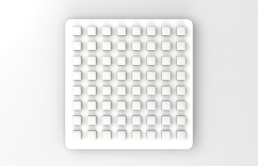
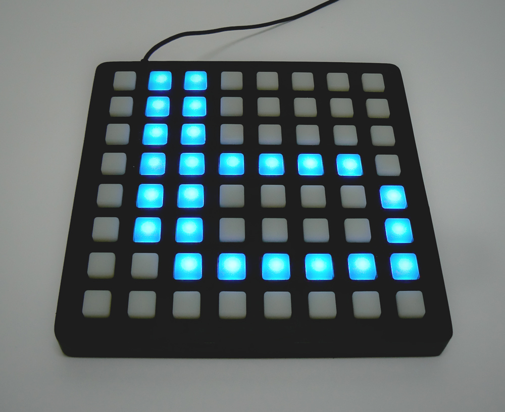
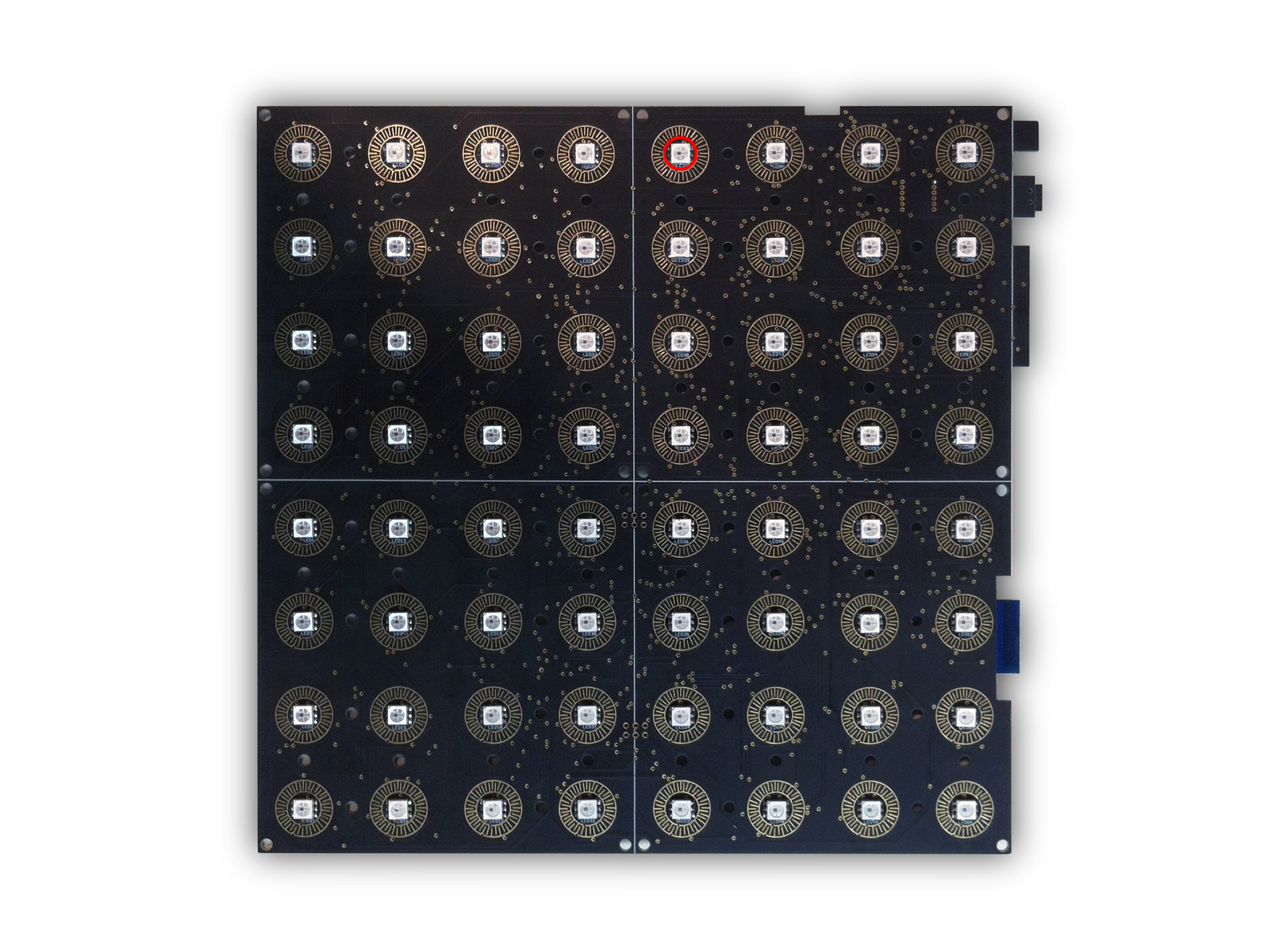
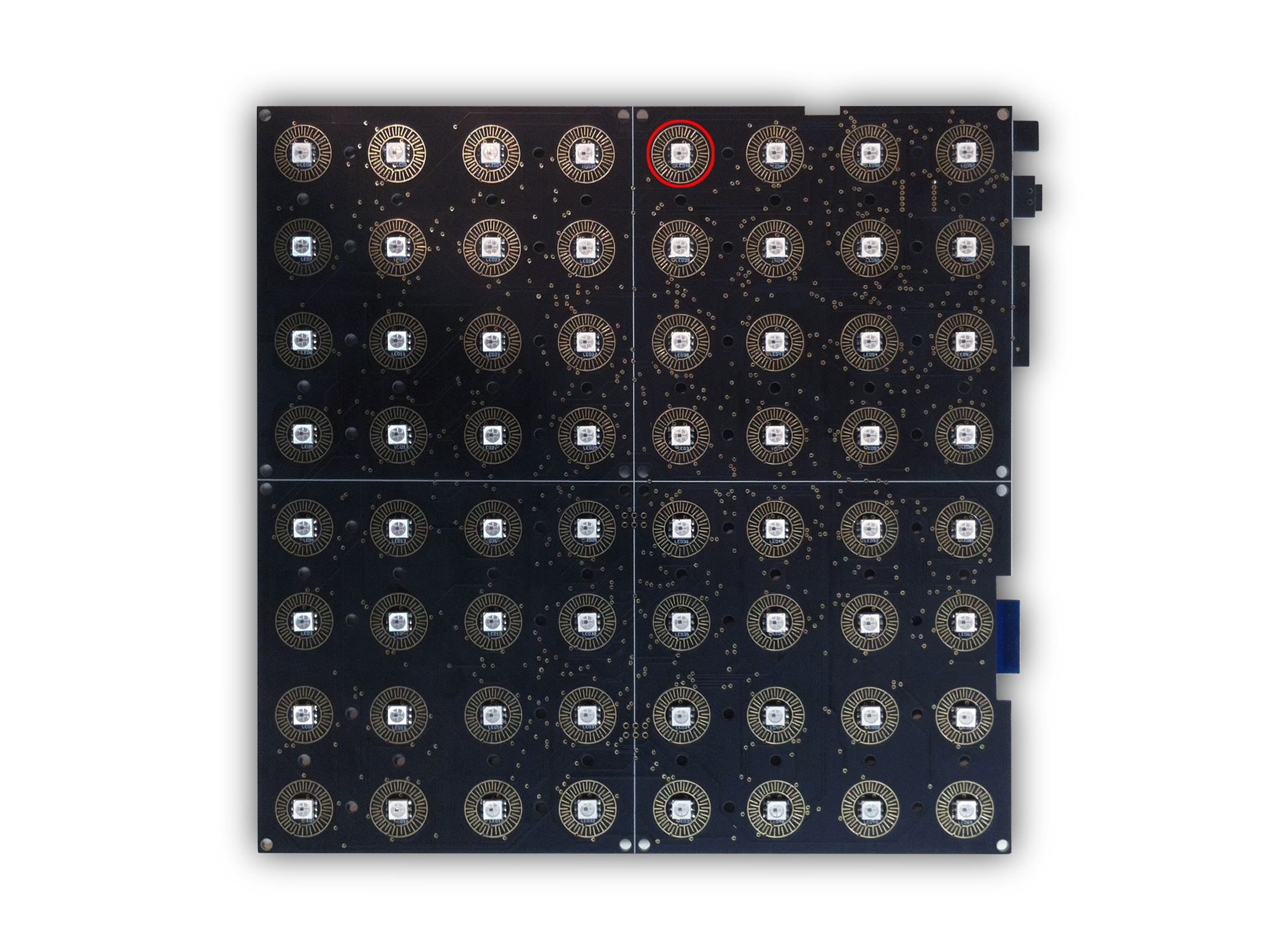
The 64 pads version of the Bhoreal Mini.
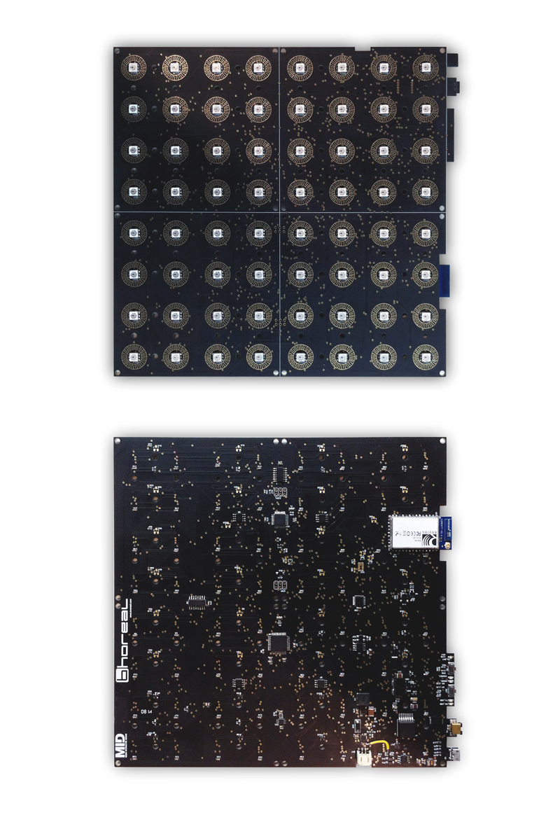
The top and bottom of the board.
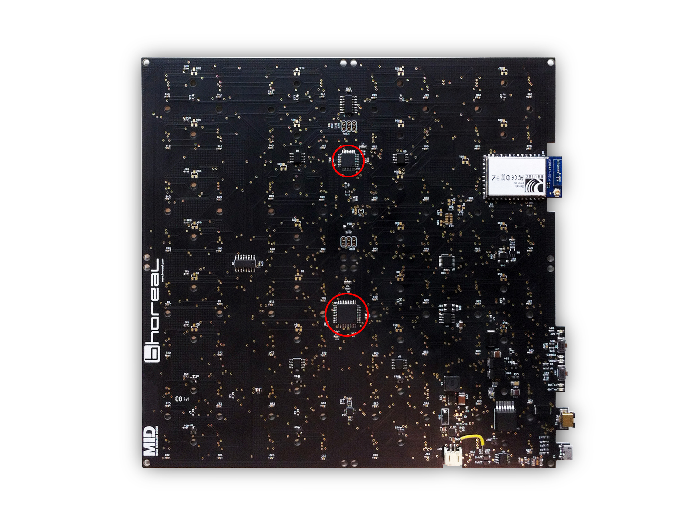
The Bhoreal Mini Slim uses two microcontrollers for its processing power. The small one is the same as used in Bhoreal Mini, the ATmega32U4, and again you can download the datasheet here.
The big one is the ATmega328, more powerfull and corresponds with the one the Arduino UNO uses. The datasheet can be checked here
Some key features from ATmega32U4:
- 16Mhz operating frequency
- 12 KB of Flash memory
- 8-bit AVR
- 2.5 KB of SRAM
- 10 bit ADC
- USB 2.0 full-speed interface
- USART, SPI and I2C interfaces
- JTAG Debug mode
And some key features from ATmega328:
- 20Mhz operating frequency
- 32 KB of Flash memory
- 8-bit AVR
- 2 KB of SRAM
- 10 bit ADC
- USART, SPI and I2C interfaces
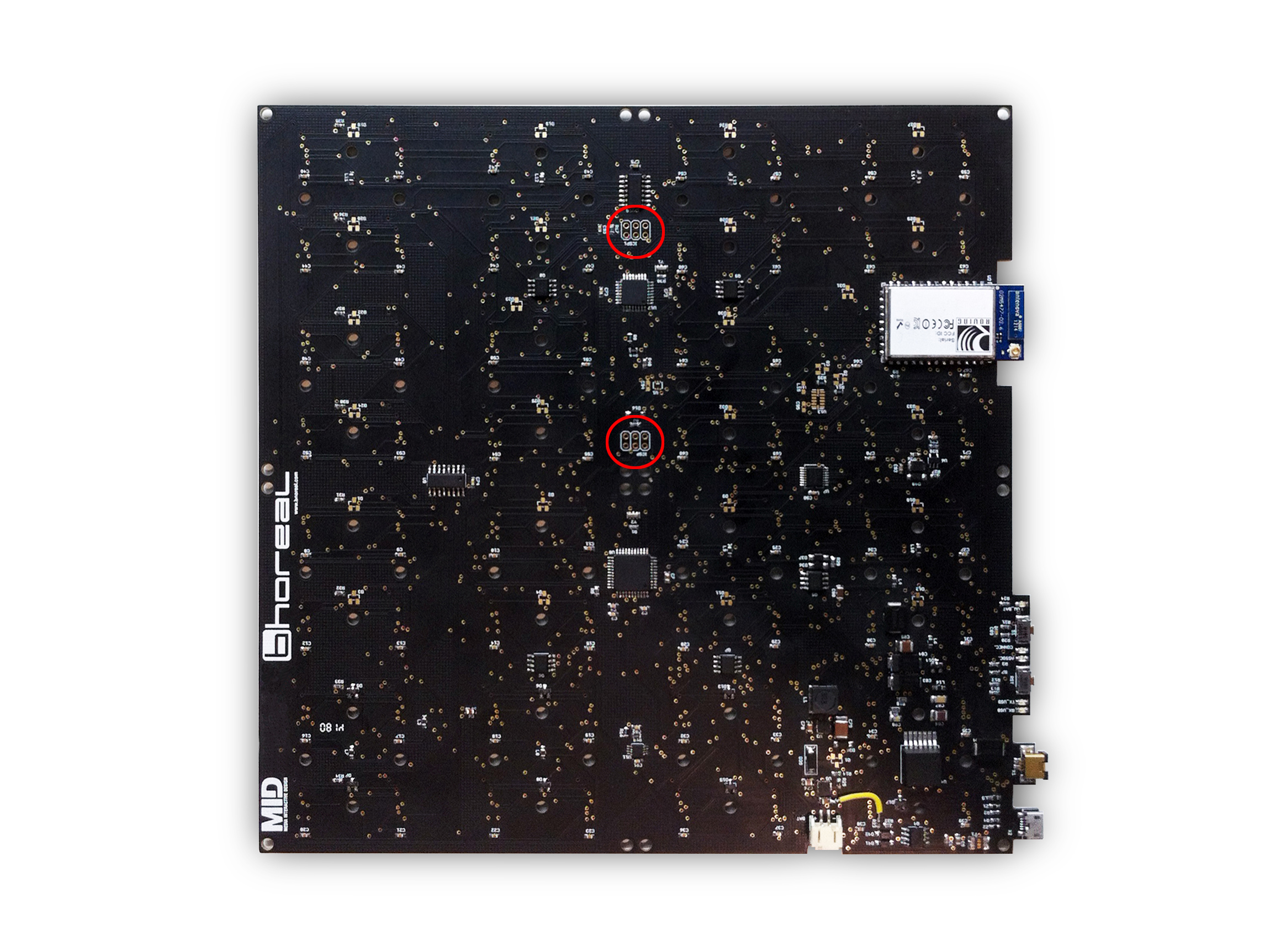
The connector In Circuit Serial Programming or commonly called ICSP allows to reprogram both microcontroller ATmega32U4 and ATmega328 from a compatible external programmer, and that is why in the Slim model appear two ICPSs. This method allows to restore the device bootloader completely or update it, if it’s necessary.
Same as Bhoreal Mini, 64 for this one.
Bhoreal Slim incorporates 64 SMD RGB digital LEDs, 2 yellow LEDs for signals and another 3 red and blue LEDs for power and communication indication. In case of RGB digital LED, the used model is the WS2812 with 6 pins. They stand out because of the use of the control chip wS2811, embed within the LED, simplifying a lot the external electronics and the space the boards occupy. This type of digital LEDs are waterfall direccionables. The data is transferred one by one through the DIN and DOUT pins, which work as a high-speed serial port, so, for the control of microcontroller, it only needs a data pin. The data refresh frequency is 800Kbps. The power for the LEDs and the control chip is splitted, and that allows a very fast multiplexing of the LEDs, therefore, an optimization of energy consumption.
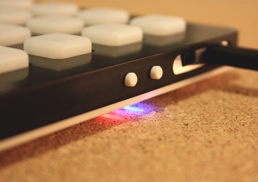
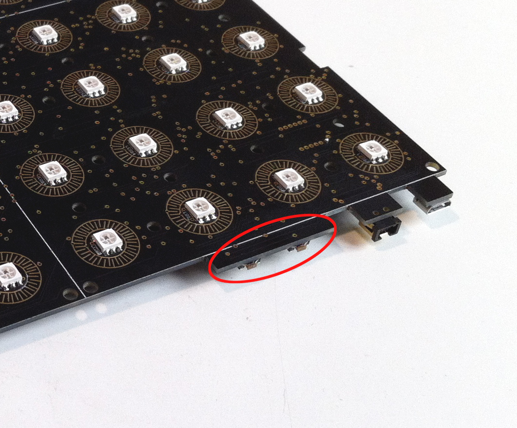
There are also two yellow LEDs on the Board to show the state of serial and MIDI communication port (they can't be seen with the case assembled); an other red LED that gets illuminated when Bhoreal is charging, and a last 2 blue LEDs for wi-fi indications purpouse. The light from the last three mentioned LEDs is visible on one side of the Bhoreal.
You can download the datasheet here.
Features:
- Viewing angle: 120 degrees
- Red: (620-630nm) @ 550-700mcd
- Green: (515-530nm) @ 1100-1400mcd
- Blue: (465-475nm) @ 200-400mcd
Forward Voltage:
- Red: 1.8-2.2V
- Green: 3.0-3.2V
- Blue: 3.2-3.4V
Bhoreal Slim has a Micro USB connector that enables the connectivity between the device and the USB communication port. Simply connect it to a computer with a micro USB cable to get started.
Same as Bhoreal Mini, 64 pads now.
The translucent silicon keypad has 16 buttons and is based on the original design of Sparkfun, and considering the perfect function with SMD WS2812 LED which are used for the Bhoreal board. Each one of the buttons has a conductive ring at the bottom that works as a switch when the conductive surfaces of the PCB is slightly pressed.
There are two keypad models adapted the different type of LEDs.
The Reset push button allows to reset the microcontroller and to reboot the firmware. This button activates the Reset circuit which is 100% compatible with Arduino Leonardo.
Next to the reset button, there is a "free" button you can program to do whatever you want. This button needs to be programmed by firmware. By default it has no action setted up, you will need to add the functions in the Bhoreal Arduino an C++. There is further information about the code in the programming environment section.
The Bhoreal Slim Pro model outstands for being wireless, using a chargeable lithium battery. It's placed over the bottom of the case, below the board, and connects to it.
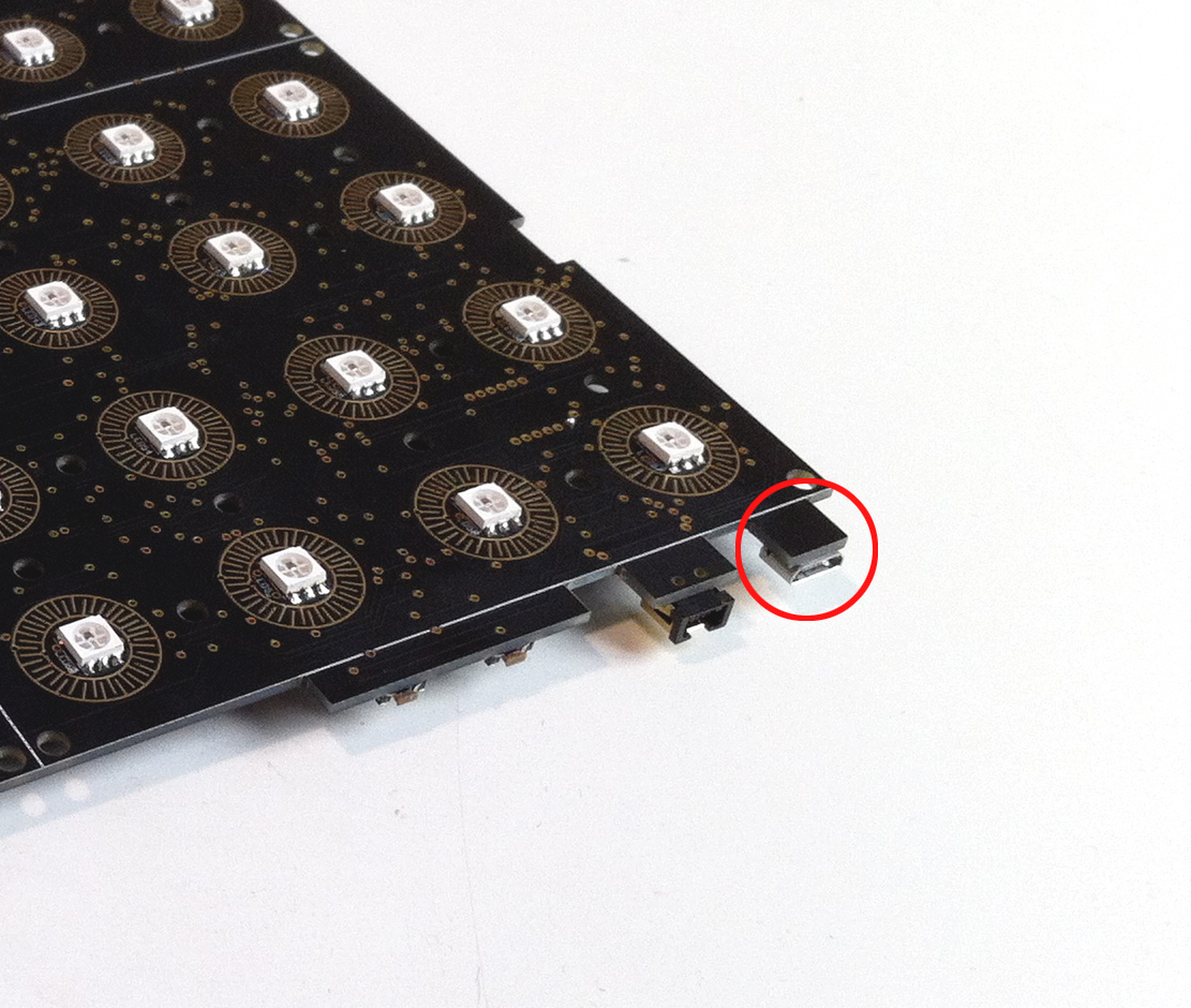
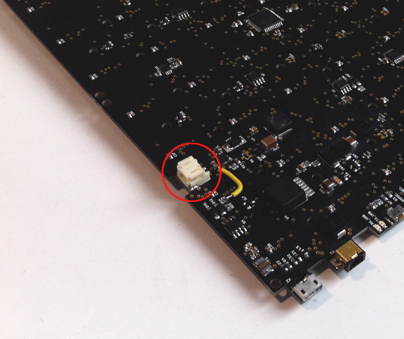
The charging of the battery goes through the board by the connector you can see in the image. A red LED illuminates on the side of the Bhoreal confirming the charging.
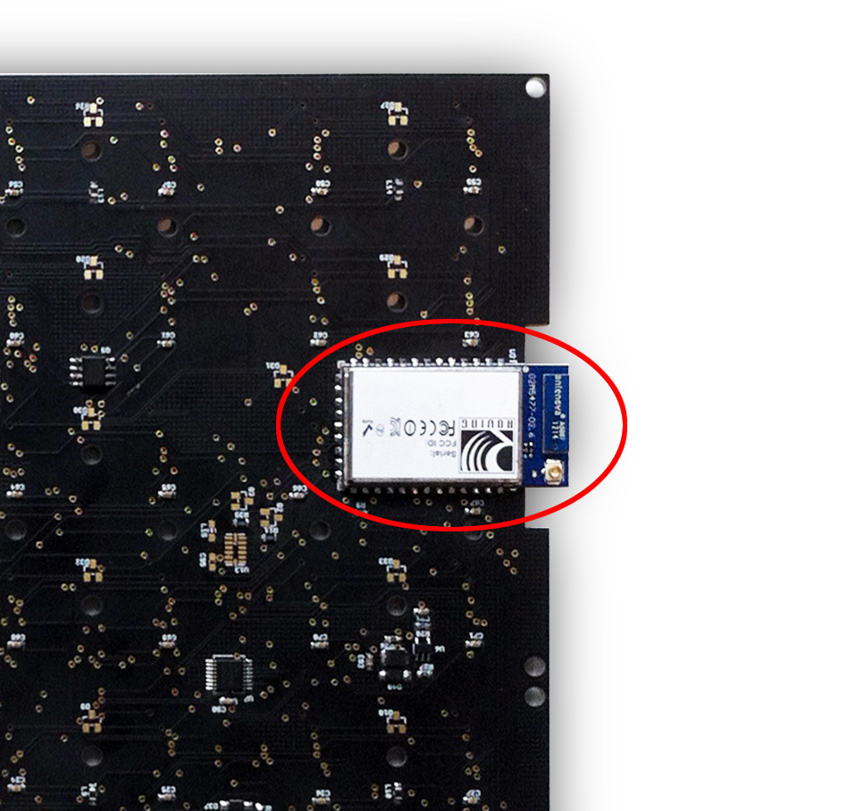
The Bhoreal Slim Pro model also has wi-fi for wireless communication, through the Wifly RN131 module. The RN131is a 80.11 b7g Wi-Fi module, low comsuption and embedded TCP/IP.
You can download the datasheet here.
The files needed for build a Bhoreal Slim board can be found here.
Under CC License.
Here is an example of the Firmware, taken from Github.
#include <Arduino.h>
#include "Bhoreal.h"

// Serial data transfer rate
#define BAUD 57600

Bhoreal Bhoreal;

void setup() {
  //Bhoreal.begin(SLIM, BAUD);
  Bhoreal.begin(BAUD);
  // Run the startup animation
  Bhoreal.startup();
}

void loop () {
  // Turn on the lights
  Bhoreal.midiRefresh();
  // Check the button states
  Bhoreal.checkButtons();
  // Check and report the ADC states, if necessary
  Bhoreal.checkADC();
}
Each one of the following pictures responds to a point of the tutorial, in the same order. First picture shows what poin 1 tells, the second one for point 2, etc.
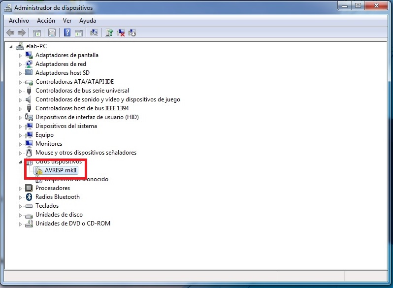
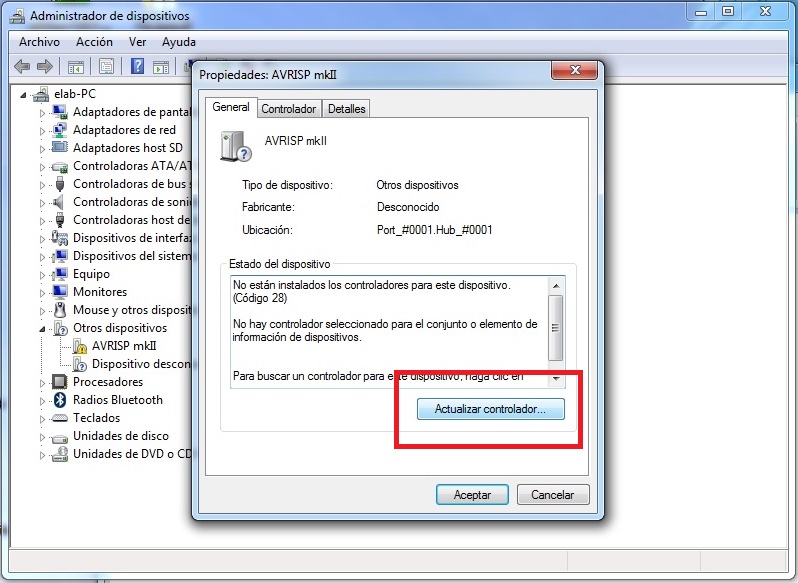
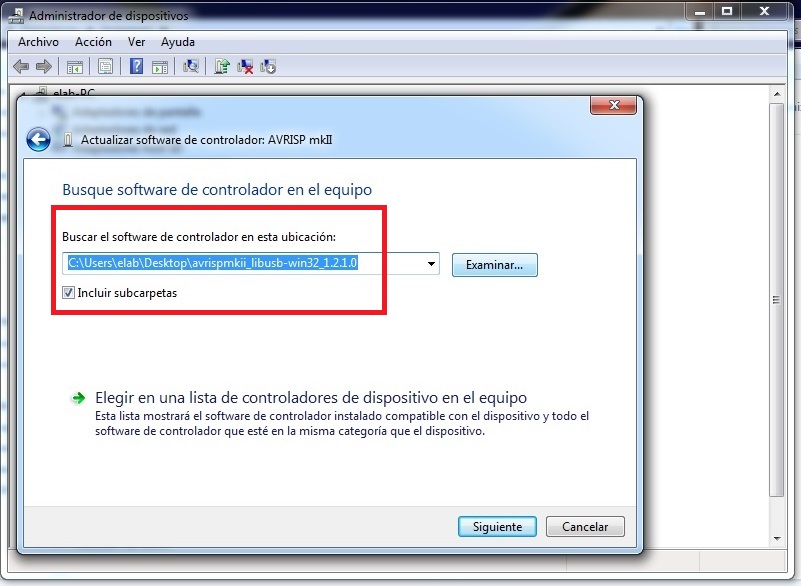
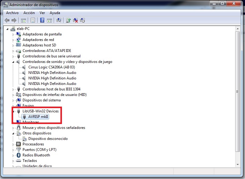
-
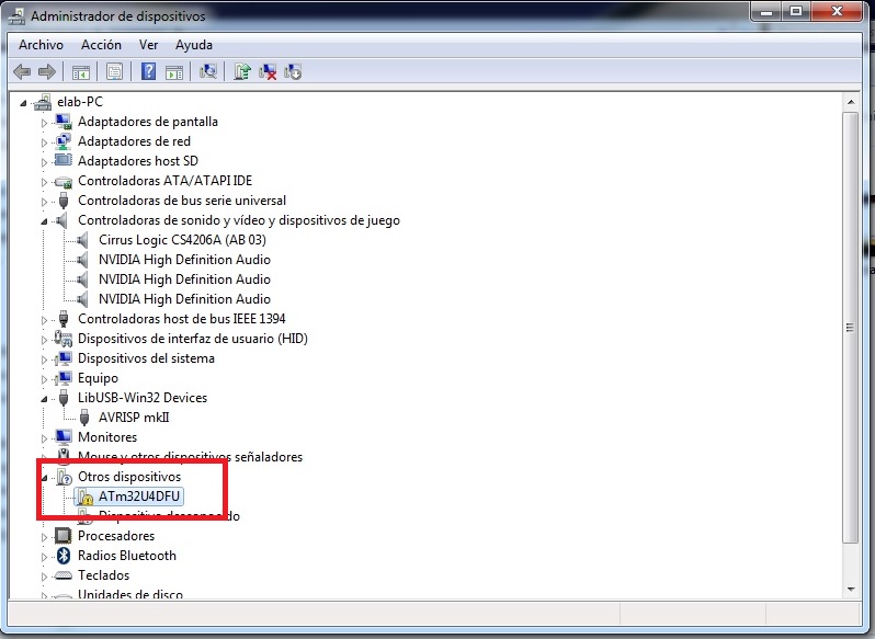
- Connect the ISP programmer to the computer Go to device administrator panel and check the device. See picture. In Windows7 the correct driver is not installed, so it’s necesary to do it before to connect.
-
- Update controller Go to properties and click the update controller button.
-
- Install the drivers Download to the desktop the drivers from this link and select the folder shown in the picture.
-
- Check the device installed Connect again the ISP programmer and check now the device configured correctly in the software.
-
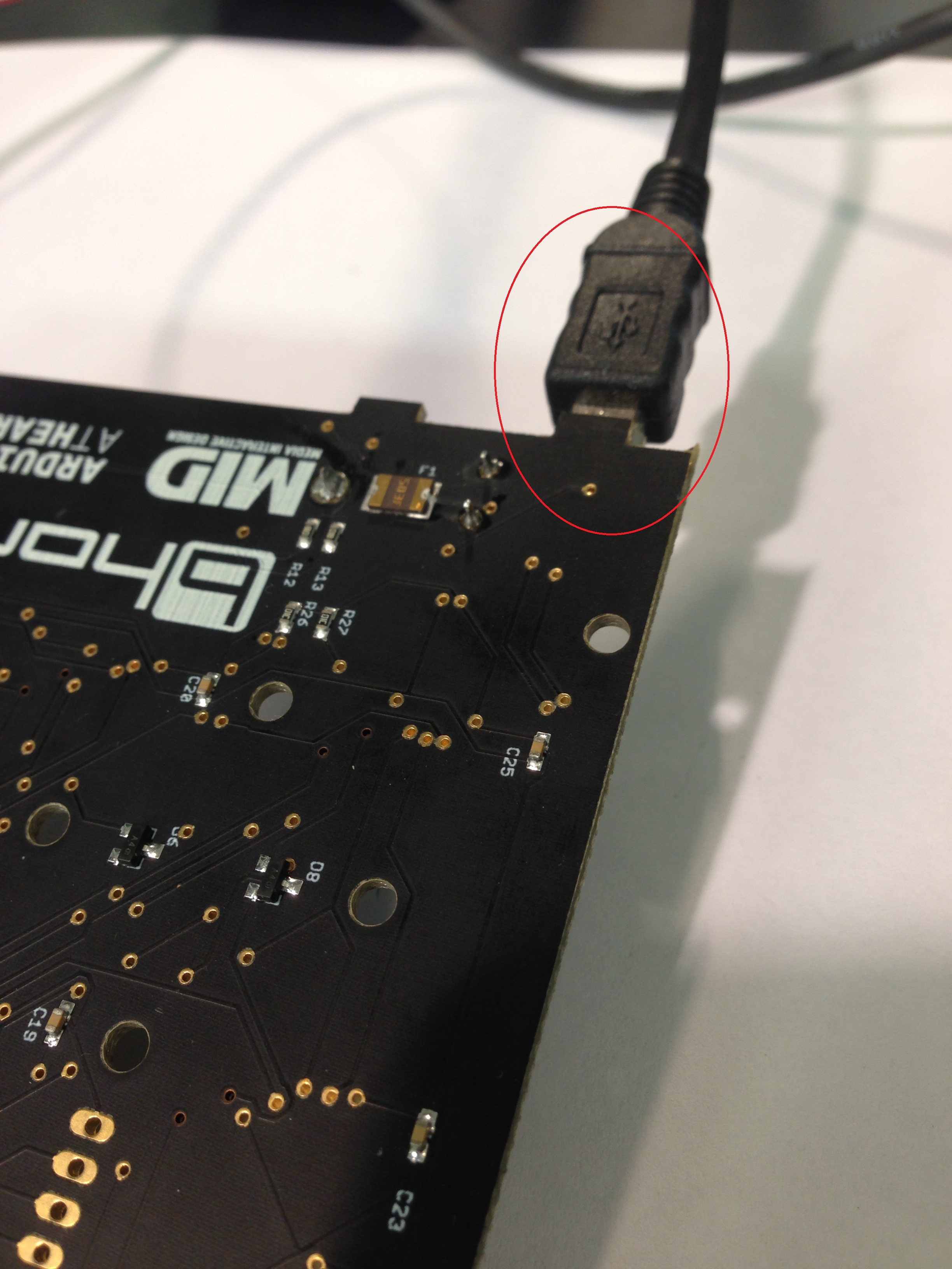
- Connect the micro USB Connect a micro USB wire to the computer.
-
- Check the Microcontroller Go to device administrator and check if the microcontroller is detected by the system.
-
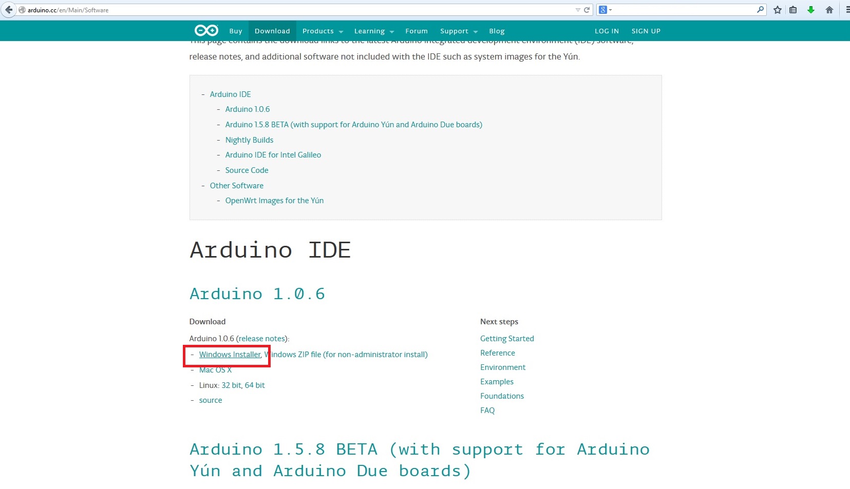
- Download the Arduino development software Go to this link and download the windows installer version.
-
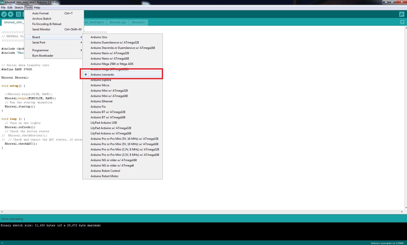
- Setup the software Install and open the software. After that, go to tools/boards and select Arduino Leonardo.
-
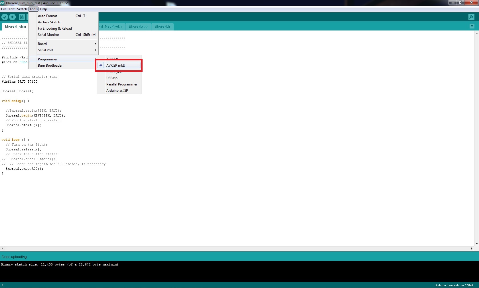
- Setup the software Go to tools/programmer and select AVRISP mkII
-
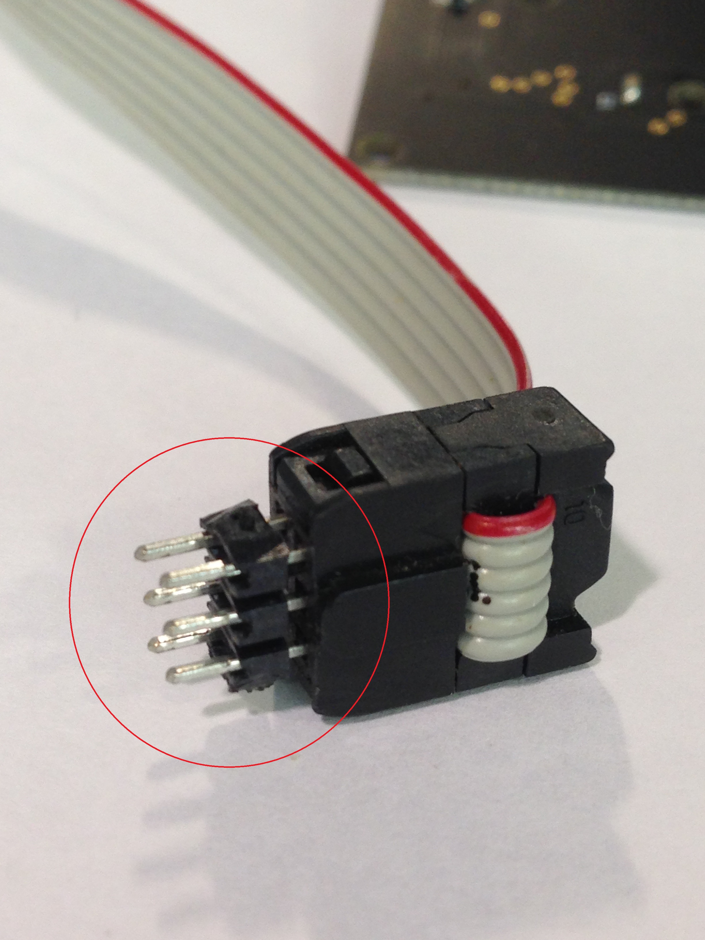
- Upload the firmware Then, prepare the ISP connector as you see in the picture. You can use a 2x6 pin array male-male.
-
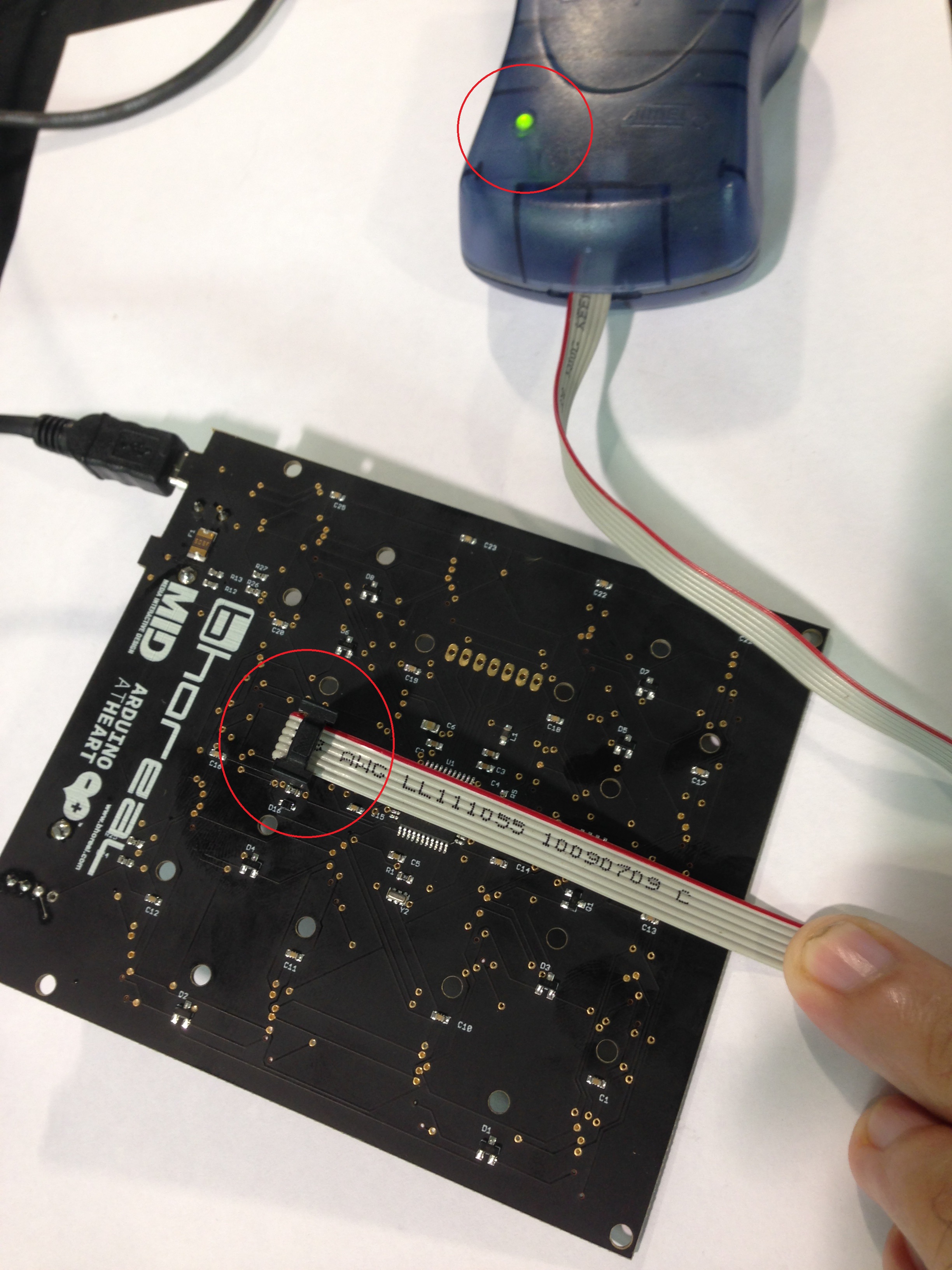
- Upload the firmware Connect the ISP connector the same way as the picture, and check if the green led of the ISP mkII is activated. Maybe you have to press laterally a little bit the ISP to ensure that there's a good contact in all the pins. Only it’s necessary a small pressure or pull the wire, like the picture.
-
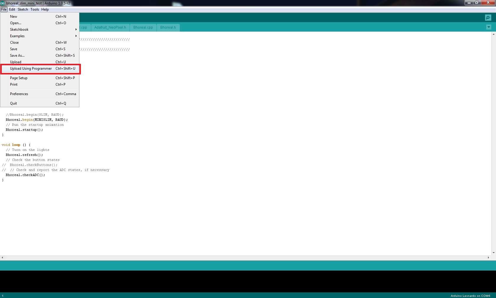
- Upload the firmware Then you have to find the firmware folder and open it into the programm. Go to file/open and find the file bhoreal_slim_mini_test.ino After this, click in file again and click into upload using programmer option. The programming will start. During the process yo have to see some leds blinking in the programmer.
-
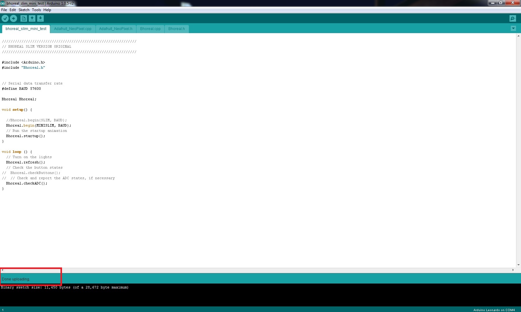
- Upload the firmware If all is ok the firmware has to be uploaded correctly. Check the message of Done Uploading!.
-
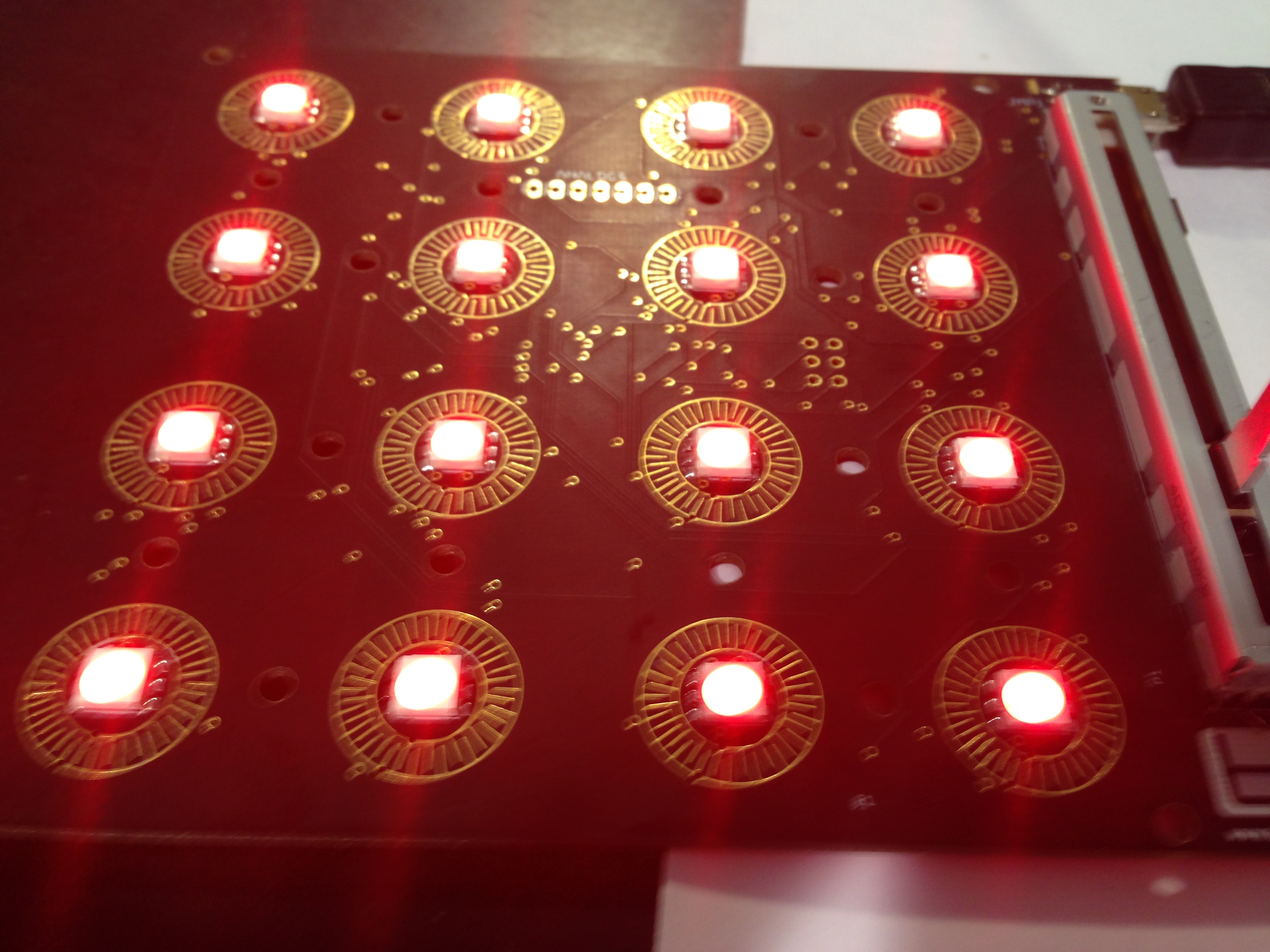
- Final test Thats it! if all the process is ok you have to see the screen test with Red, Green, Blue and white transition. At this point is recommended to wait some minutes because some times the damages LEDs stop to working with high temperature. After check you can go to the next board and come back to the point 11 of this tutorial.
Here we are going to explain a little bit about the diferent parts of the code that make Bhoreal work as it does.
As said in firmware section, Bhoreal is based on "Arduino Leonardo". The project includes the Arduino code that runs all the action, the necessary libraries for LED management, and the C++ developed libraries that build the heart of Bhoreal. Most of the code is explained in comments, so we are going just to talk about the main structure.
For correct compilation, see FLAGS settings at Libraries (bhoreal.h).
#include <Arduino.h>
#include "Bhoreal.h"

// Serial data transfer rate
#define BAUD 57600

Bhoreal Bhoreal;

void setup() {

  //Bhoreal.begin(SLIM, BAUD);
  Bhoreal.begin(BAUD);
  // Run the startup animation
  Bhoreal.startup();
}

void loop () {
  // Turn on the lights
  Bhoreal.midiRefresh();
  // Check the button states
  Bhoreal.checkButtons();
  // Check and report the ADC states, if necessary
  Bhoreal.checkADC();
}
Here we have a simple set of functions that call the huge ones from the libraries.
Adafruit_Neopixel.cpp and Adafruit_Neopixel.h form the library developed by Adafruit Company that is used to control the "neopixel" LED in Bhoral. You can learn far more from their website and check the code at their github, so we are not going to go deep further here.
The flags for correct Bhoreal working and core function definitions live here. In firmware section we already talked about the MIDI and Serial configuration, but now is time to explain how to choose your Bhoreal model.
Below the MIDI and Serial flags, there are another three that distinguish between Bhoreal models.
#define MINI  	  0  // Matrix size
#define MINISLIM  1  // Matrix size
#define SLIM  	  2  // Matrix size
In order to let the board know which part of the code it should use (the one for the Mini model, or the one for the Slim model), under the previous definitions, comment and de-comment the flags that match your model.
#define  MODEL  MINISLIM //Model
//#define  MODEL  SLIM 	 //Model
The remaining code corresponds to the definition of functions that make Bhoreal work.
### Bhoreal.cpp
As an overview of the main functions that loops in the Bhoreal Arduino's program.
Bhoeal.begin(BAUD)
Starts the communiaction between the Bhoreal and the computer, and other functionalities.
- Sets the configuration (
INPUT/OUTPUT) of the Arduino's pins, depending on which model. - Starts the LEDs.
- Starts Serial caommunication (if the flag indicate it).
Bhoreal.startup()
Makes the initial led animation
Bhoreal.midiRefresh()
Checks for the incoming MIDI (or Serial, if chosen) and updates the color from the pads.
Bhoreal.checkButtons()
Sends to the computer the info about any pressing and unpressing action on the buttons.
This takes place by reading the state of all the pads, and calling the funcitons Bhoreal::on_press() and Bhoreal::on_release(), depending on the state, which send the corresponding MIDI message with MIDIEvent and MIDIUSB.USB().
Bhoreal.checkADC()
The same way as the checkButtons function, this one reads the Slider as an analog input, and sends de MIDI of it's position.
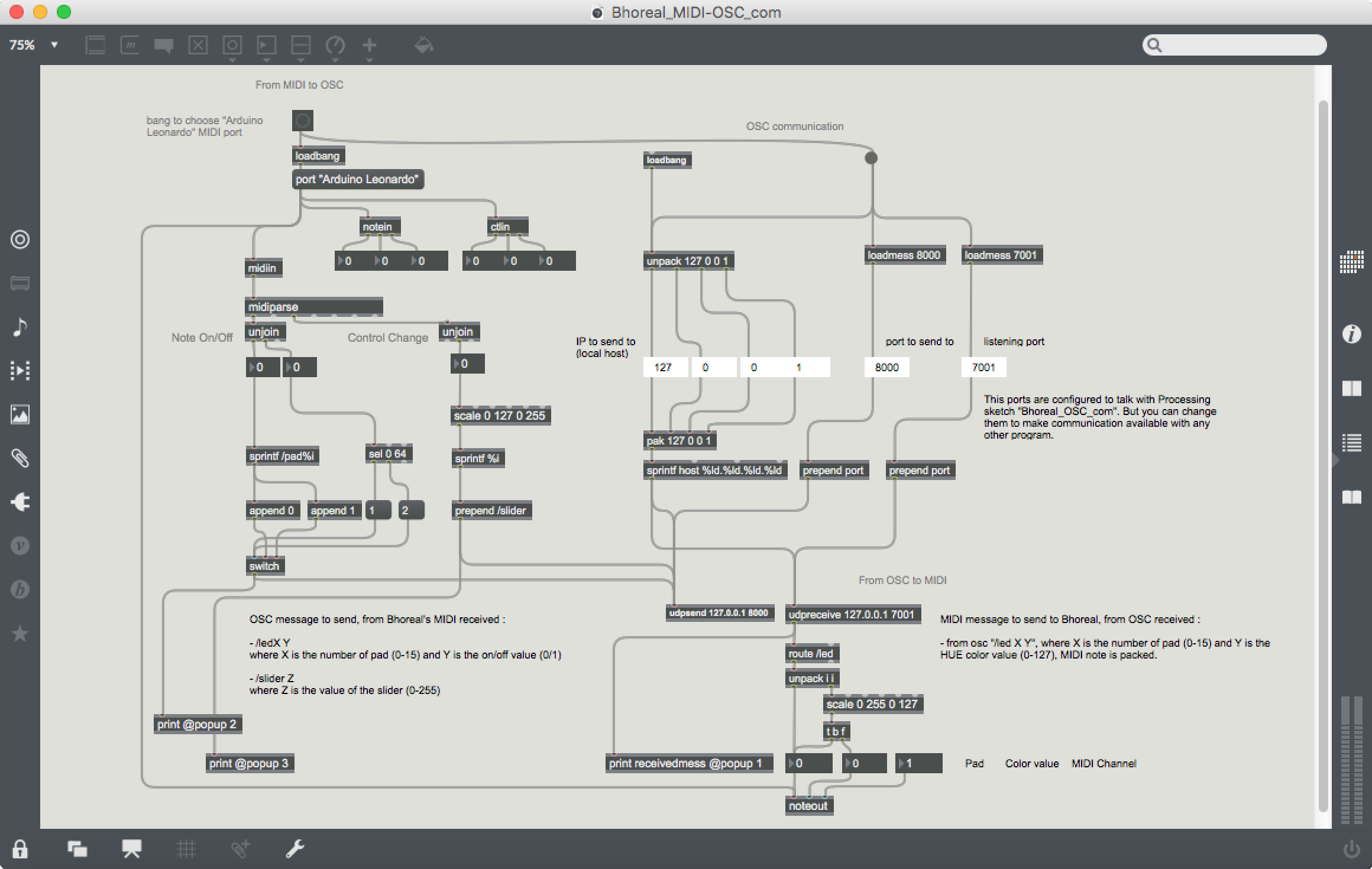
A patch in MAX that takes the incoming MIDI messages from Bhoreal, turn them into OSC and send them from the selected port; the same way it takes the OSC messages received in a chosen port, and send the corresponding MIDI to Bhoreal.
Bhoreal MAX MIDI-OSC Router at github
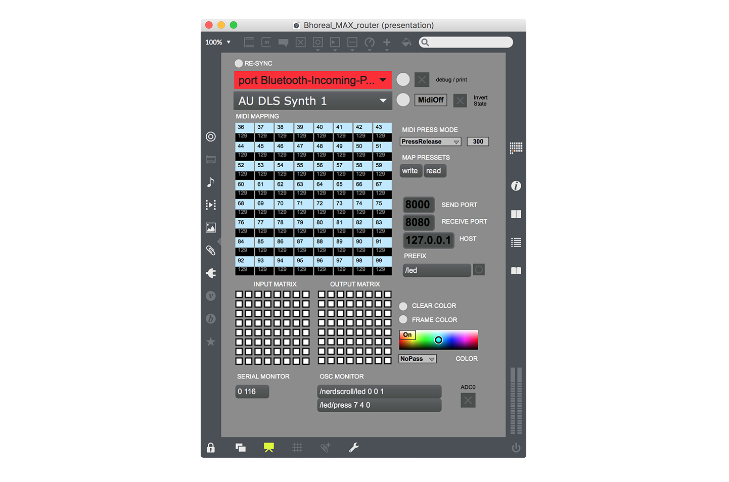
There is also a router patch that works with the serial communication (second image). This needs the serial flags to be true.
Bhoreal MAX Serial Router at github
// if OSC is received
void oscEvent(OscMessage theOscMessage) {

  if( theOscMessage.addrPattern().equals("/led")) {
    channel = 1;                                  // the channel
    pitch = theOscMessage.get(0).intValue();      // the pad
    velocity = theOscMessage.get(1).intValue();   // the color
    note.setChannel(channel);
    note.setPitch(pitch);
    note.setVelocity(velocity);
    // send the MIDI
    myBus.sendNoteOn(note);
  }
}

// if MIDI noteOn is received (very similar for noteOff)

void noteOn(Note note) {
  // turn into OSC
  OscMessage myMessage = new OscMessage("/pad"+ str(note.pitch()));  // /padX, where X is the number of pad (0-15)
  if(note.velocity() == 64) {myMessage.add(1);}                      // value of the pad pressed/unpressed (1/0)
  else {myMessage.add(0);}
  oscP5.send(myMessage, tosendAdress);
}

// if MIDI CC is received

void controllerChange(ControlChange change) {
  // turn into OSC
  OscMessage myMessage = new OscMessage("/slider"+ str(note.pitch()));  // /slider, a Control Change value
  myMessage.add(map(change.value(), 0, 127, 0, 255));                   // the CC value of the slider (0-255)
  oscP5.send(myMessage, tosendAdress);
}
A Processing sketch that takes MIDI from Bhoreal and sends OSC wherever you want by a selected port, and also does the inverse way.
It comes with a small graphic interface that shows the incoming MIDI data on the left matrix + slider and offers the posibility of sending MIDI on the right matrix + slider.
Bhoreal Processing Router at github
Between all the code for setup, communication and graphic help, you can check the important functions here.
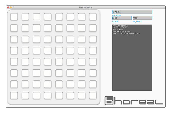
A Processing sketch that emulates the Bhoreal SLIM, where you can press the pads and see the sended OSC messages. Needs serial communication to be activated.
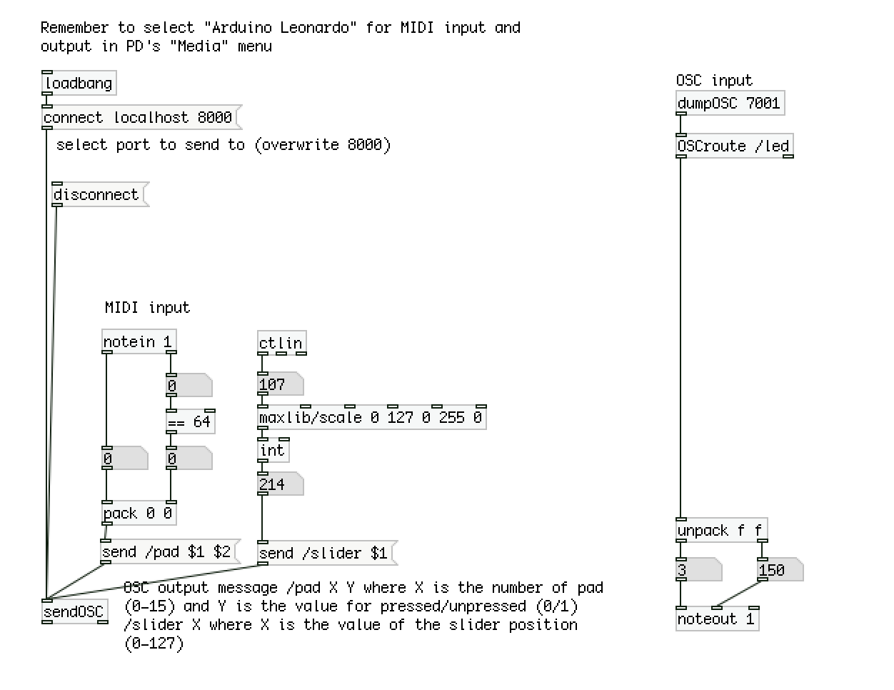
A patch in PD that takes the incoming MIDI messages from Bhoreal, turn them into OSC and send them from the selected port; the same way it takes the OSC messages received in a chosen port, and send the corresponding MIDI to Bhoreal.
Bhoreal PureData MIDI-OSC Router at github
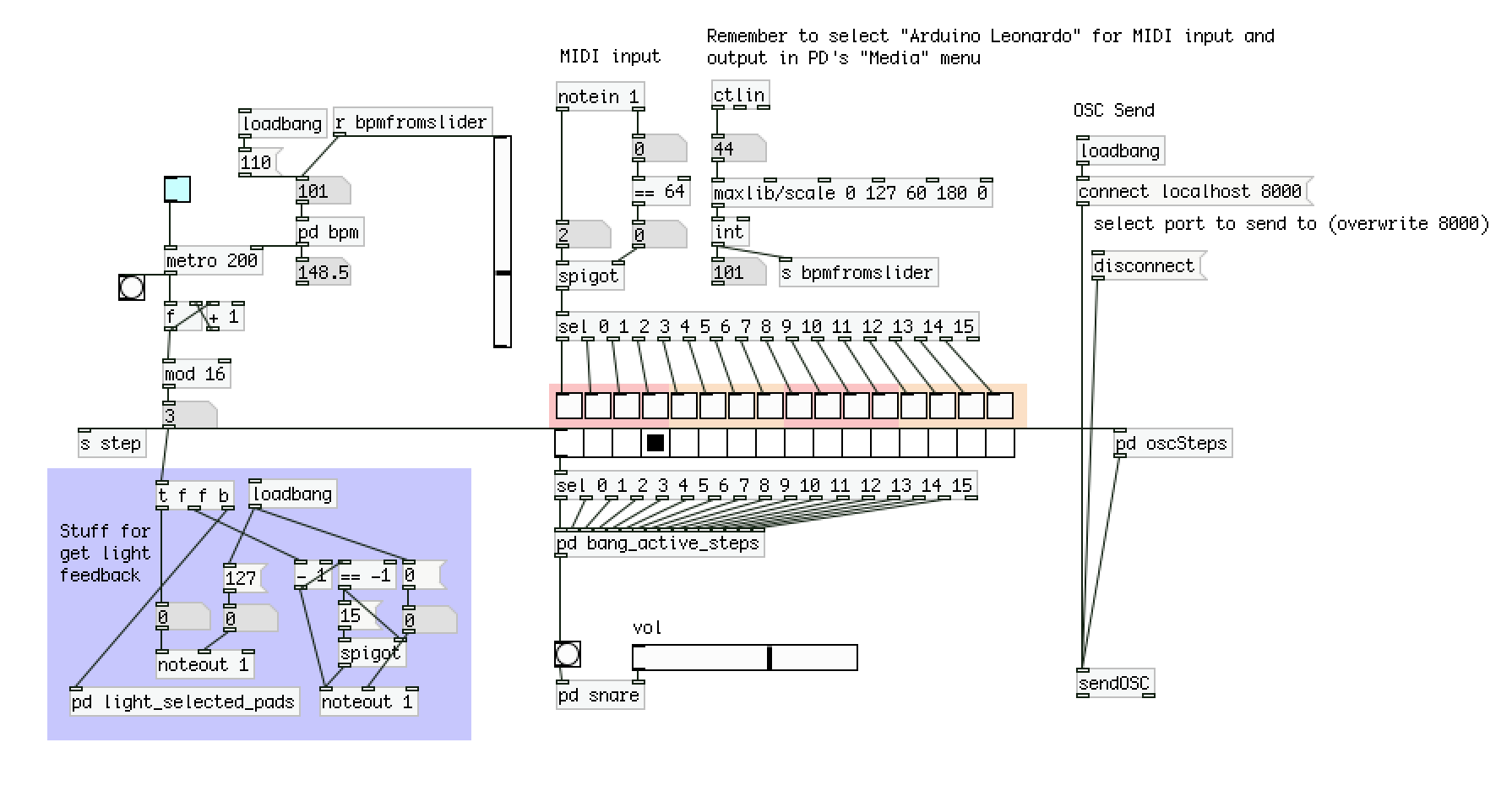
A small program y PD that runs a step sequencer over the 16 patches, following a selected BPM. The light traveling along the pads indicates the step. You can press any patch and get light feedback.
In the program the MIDI triggers a snare sound, just for test. There principal aim of the PD patch is to send OSC, as it does.
You are free to implement a MIDI-clock-sync system (you can use the object [midiinrealtime]) and add funcionality for get 32 and 64 steps (2 and 4 beats).
