!> This feature is not included in precompiled binaries.
To use it you must compile your build. Add the following to user_config_override.h:
#ifndef USE_SHUTTER
#define USE_SHUTTER           // Add Shutter support (+6k code)
#endif
Stepper motors can be used to operate shutters and blinds. The configuration is very similar to the Circuit Safe (Shuttermode 1) configuration. To operate a stepper motor requires driver module such as the A4988 and uses EN (enable), DIR (direction), STP (Stepper) for controls. If everything is defined correctly the shuttermode 3 will be reported at boot time.
Tasmota supports a maximum of four shutters with one stepper motor per shutter. Each stepper connected to a Tasmota device must use the same stepper driver and motor. You cannot move more than one shutter concurrently.
- Full description of Blinds and Shutters
- Complete list of Blinds, Shutters and Roller Shades Commands
- Stepper motor and Stepper drivers wiring diagrams
- Stepper drivers configuration tutorials:
- Modifying a 28BYJ-48 12V stepper motor from unipolar to bipolar tutorial
- Bill of Materials
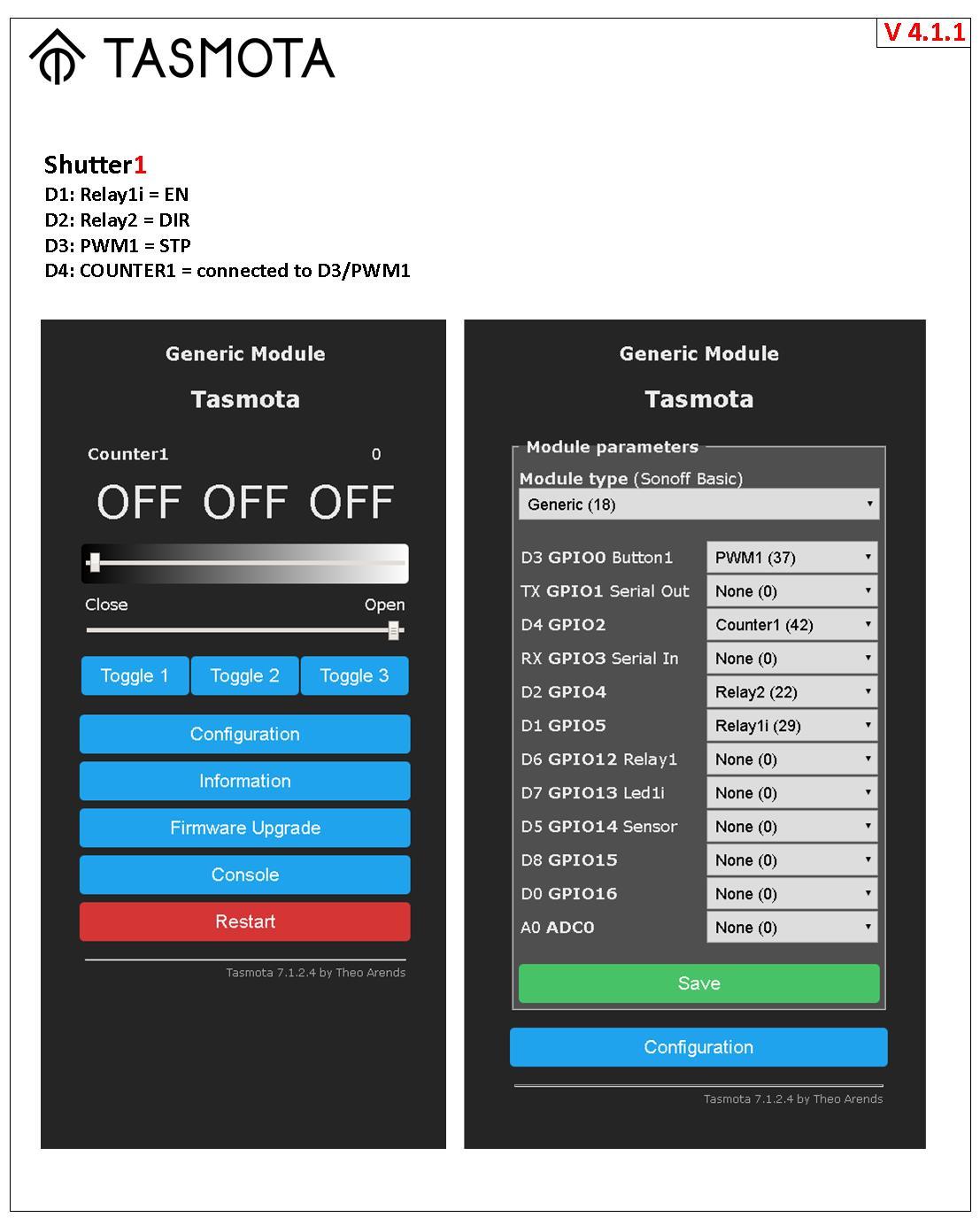
EN and DIR are on Relay1i and Relay2 respectively. Please be aware to use the inverse relay for the enable signal.
The STP signal is assigned as a PWM<x> component where <x> matches the number of the shutter (e.g., PWM1 for Shutter1). The shutter feature adjusts the PWM frequency to operate the motor for proper shutter operation. The stepper motor frequency setting is a global setting all PWM components on the device. This means that all shutters on the device will operate at the same speed. Therefore no PWM devices other than shutters can be connected to the same Tasmota device.
The frequency of the PWM can be changed from 1000Hz to any value up to 10,000Hz. The command ShutterFrequency globally changes this. Be aware that most 12V operated motors cannot work faster than 2,000Hz. 5,000Hz.10,000Hz is possible by increasing the supplied voltage to 24V and use ShutterMotorDelay to allow a slow speed up/speed down. The maximum voltage of the A4988 is 36V.
Finally a GPIO must be assigned as Counter1. This counter is used to keep track of the steps and send the stepper to the correct position. The Counter1 GPIO must be connected to the PWM1 GPIO. Otherwise the stepper and your shutter will run continually or freeze up randomly.
Only bipolar stepper motors may be used (see above).
You must properly configure the stepper motor driver (see above).
ShutterOpenDuration and ShutterCloseDuration can be different. e.g. for a slower close than open.
You can define a soft start/stop by defining a ShutterMotorDelay. This causes the driver to ramp the speed up and down during the defined duration. The change of the ShutterMotorDelay does NOT change the WAY the shutter makes. This is very convinent to trim the accelerate and decelerate rate without changeing the way.
| Wemos Pin | GPIO | Component | Stepper Signal |
|---|---|---|---|
| D1 | 5 | Relay1i | EN |
| D2 | 4 | Relay2 | DIR |
| D3 | 0 | PWM1 | STP |
| D4 | 2 | Counter1 | STP |
a) Set ShutterMode 3
Backlog PulseTime1 0; PulseTime2 0 // for relay Relay1i and Relay2
Interlock OFF // this is a global variable for all Relays or at least the RELAYS NOT in the Interlock group
PWM1 and COUNTER1 defined
b) Enable Shutters
SetOption80 1 // this is a global variable for all Shutters
c) Configure Shutter 1 and test ShutterMode 1 is working
ShutterRelay1 1 // for relay Relay1i and Relay2
d) Set the stepper motor speed (optional setting)
ShutterFrequency 1500 // this is a global variable for all steppers (1000rpm by default)
e) Set at least a small ramp-up/ramp down period 1.0 second (optional)
ShutterMotorDelay1 1.0 // Stepper do not like infinite momentum. Ramp up/down speed allow much higher frequencies.
f) Restart Tasmota
Restart 1
g) Test the shutter
ShutterOpen1
ShutterStop1 // to stop the STEPPER1
ShutterClose1
ShutterInvert1 // to change the direction of rotation of the STEPPER1
h) Perform the shutter calibration
You must first set up the first shutter and only then the next.
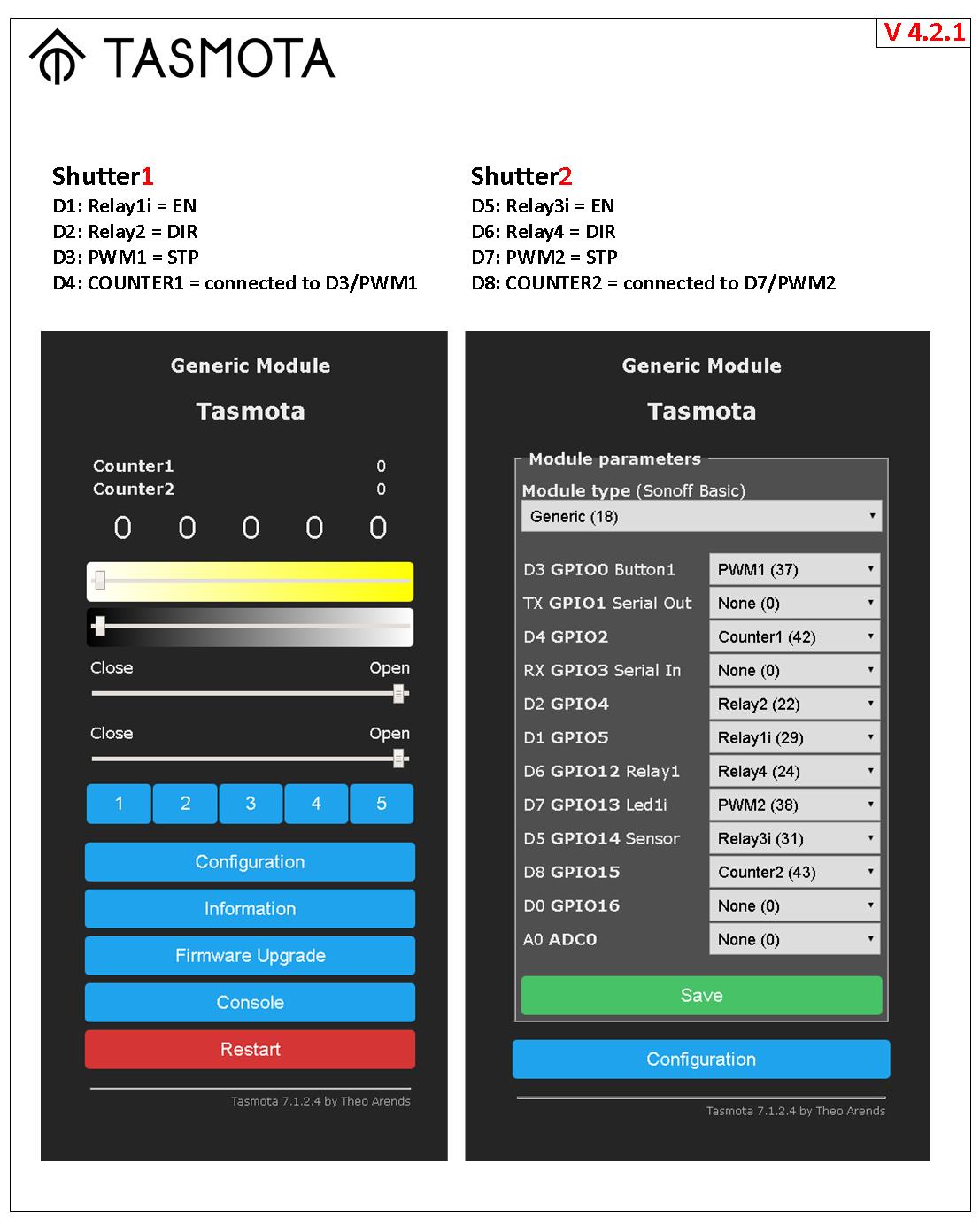
| Wemos Pin | GPIO | Component | Stepper Signal |
|---|---|---|---|
| D5 | 14 | Relay3i | EN |
| D6 | 12 | Relay4 | DIR |
| D7 | 13 | PWM2 | STP |
| D8 | 15 | Counter2 | STP |
a) Set ShutterMode 3
Backlog PulseTime3 0; PulseTime4 0 // for relay Relay3i and Relay4
PWM2 and COUNTER2 defined
c) Configure Shutter 2 and test ShutterMode 1 is working
ShutterRelay2 3 // for relay Relay3i and Relay4
b) Restart Tasmota
Restart 1
d) Test the shutter
ShutterOpen2
ShutterStop2 // to stop the STEPPER2
ShutterClose2
ShutterInvert2 // to change the direction of rotation of the STEPPER2
e) Perform the shutter calibration
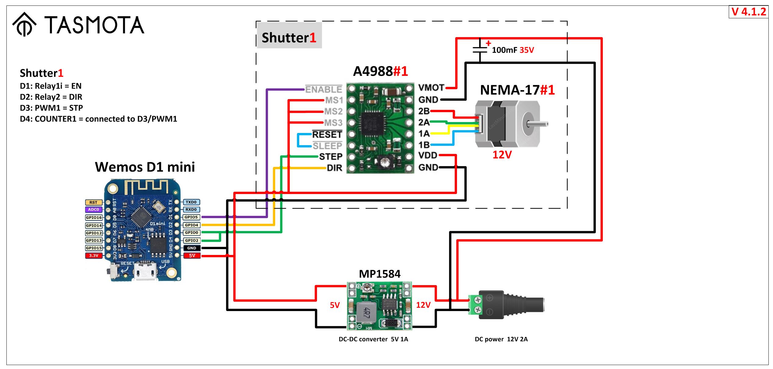
- Diagram v412: simple universal setup. For example, the control of horizontal curtain or vertical shutters, blinds adjuster or window opener, pet feeders, opening of a water tap for watering the lawn, rotating table for subject photography, opening the ventilation flap, PTZ camera, 3D Scanner Table, linear Actuator.
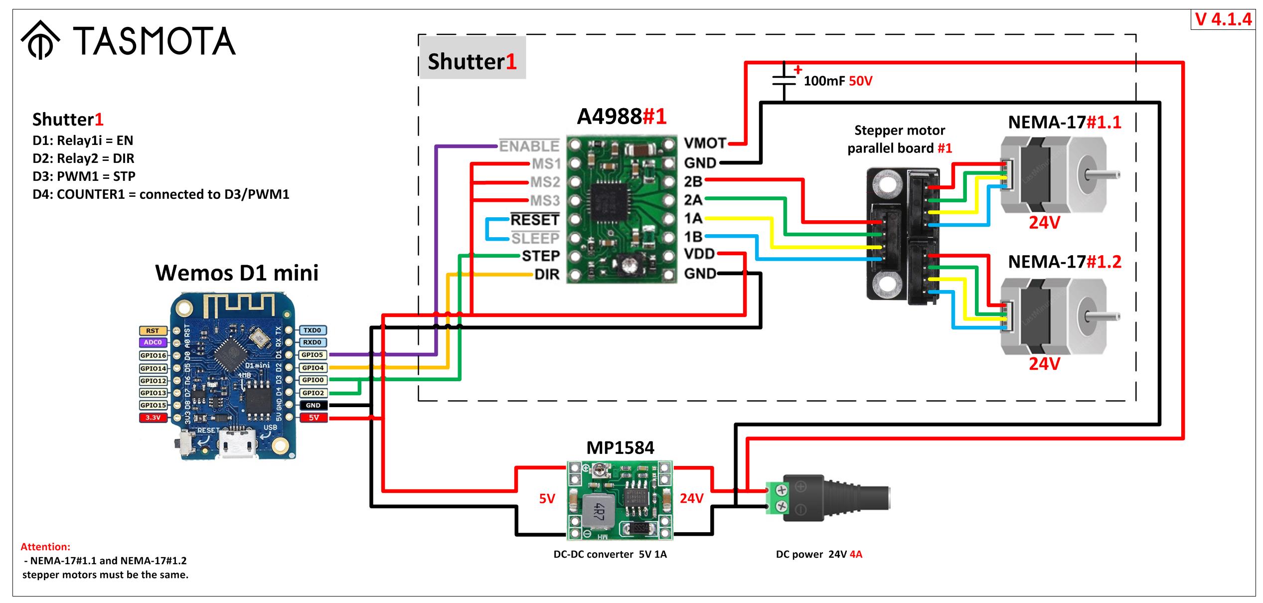
- Diagram v414: parallel setup is to run two parallel steppers motors from the same controller. For example, to control a large and heavy hanging screen for an LCD projector, or two curtains at once on one large window.
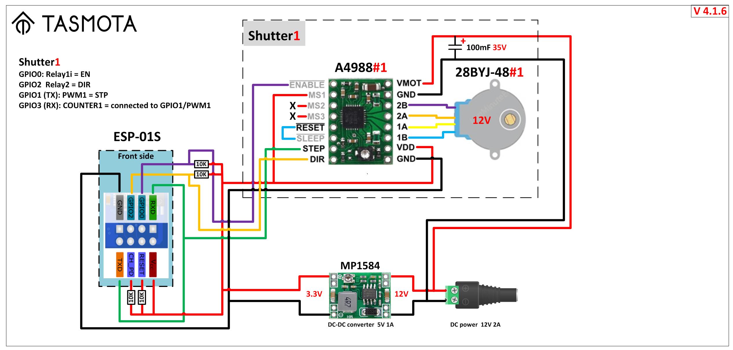
- Diagram v416: minimum setup size. For example, for small curtains located in a limited space.
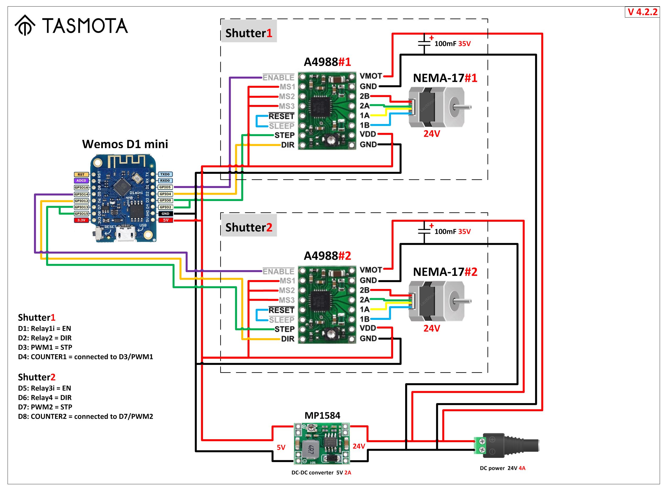
- Diagram v422: parallel setup is to run two shutters and independent control of two stepper motors from one controller. For example, to control two independent curtains.
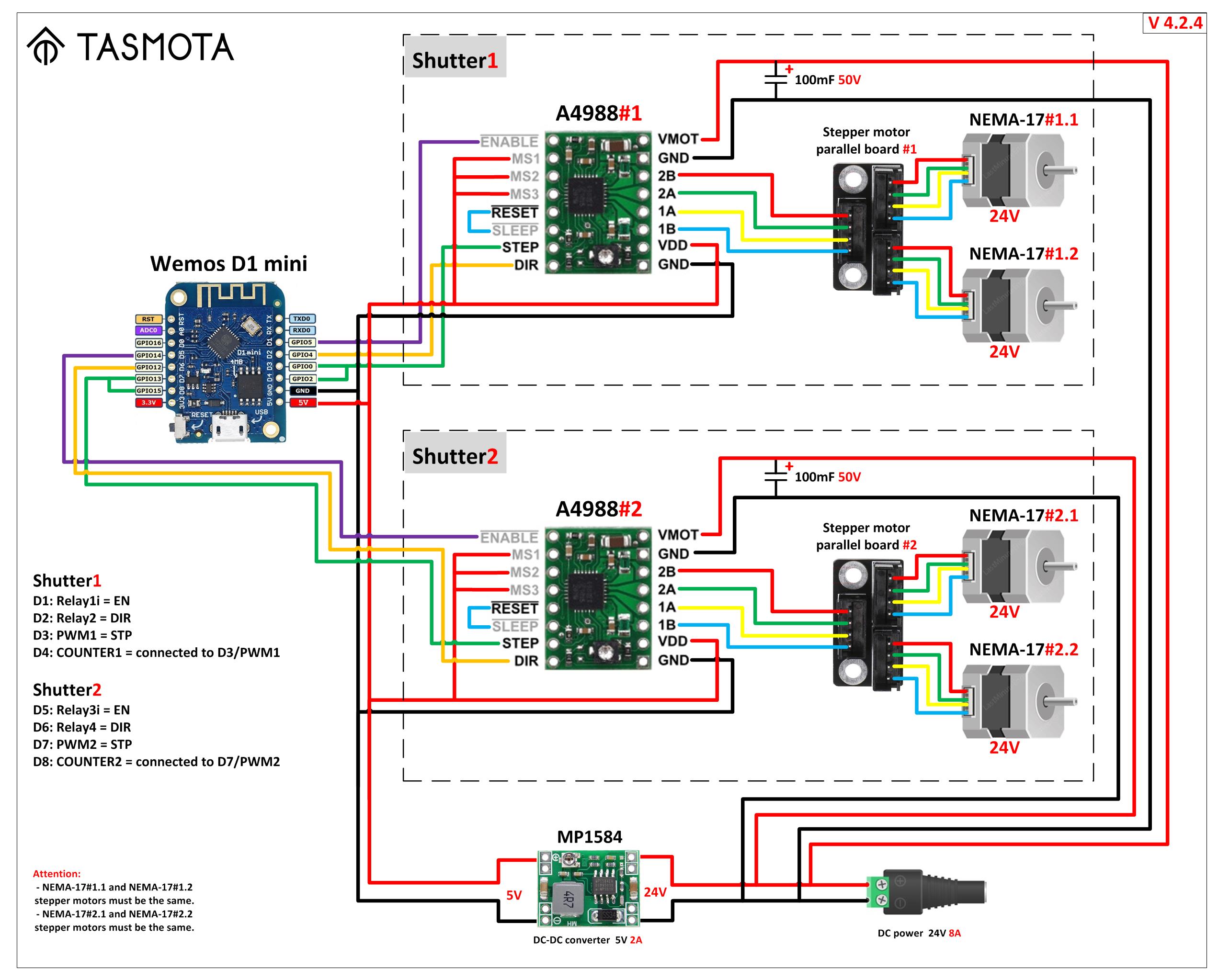
- Diagram v424: big parallel setup is to run two shutters and independent control of two pairs of stepper motors from one controller. For example, to control four curtains on one very large window.
- ESP8266 Boards:
- Stepper motors (NEMA 17):
- Stepper motors (28BYJ-48):
- Stepper Drivers:
- Stepper Motor Control Development Boards:
- DC-DC Step Down Power Supply Module:
- Power Supplies (AC-DC):
- Aluminum Capacitors:
- Motor Testing PWM Signal Generator:
